

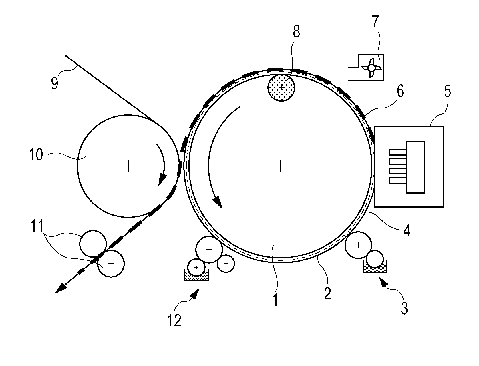
Transfer inkjet recording method
a technology of inkjet and recording method, which is applied in the field of transfer inkjet recording method, can solve the problems of inability to uniformly apply an aggregating agent to a highly releasable image-forming face, the pitch of the lyophilic portion (center-to-center distance between the lyophilic portion) cannot be reduced to less than the diameter, and the image is easily wetted with ink. , to prevent the deformation of ink dots, the variation of reproduction resolution
- Summary
- Abstract
- Description
- Claims
- Application Information
AI Technical Summary
Benefits of technology
Problems solved by technology
Method used
Image

Examples
example 1
(a) Patterning of Image-Forming Face of Intermediate Transfer Member
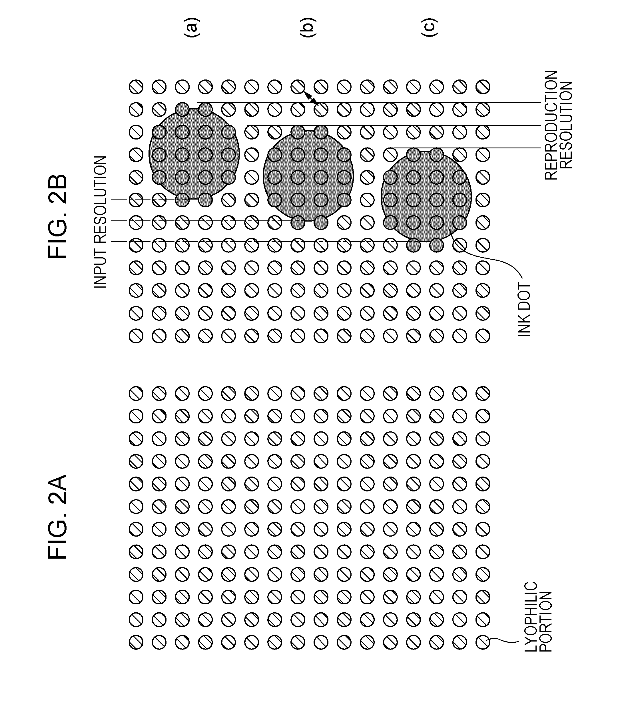
[0065]A pattern including lyophilic portions and a lyophobic portion was formed on the image-forming face of an intermediate transfer member. First, the surface of a 0.4 mm thick PET film was coated with a silicone rubber having a hardness of 40° (KE-1310, produced by Shin-Etsu Chemical) at a thickness of 0.2 mm. The resulting film was used as the intermediate transfer member. A resist layer was formed over the entire surface (image-forming face) of the intermediate transfer member to a thickness of 0.5 μm by applying a positive resist (OFPR-700, produced by Tokyo Ohka Kogyo) using a spin coater, and then drying the resist. The dried resist layer was exposed to light through a photomask having the pattern shown in FIG. 5A (regions for lyophilic portions are open). The pattern to be formed was as follows:[0066]Small lyophilic portions: diameter of 12 μm, pitch of 1200 dpi[0067]Large lyophilic portions: diameter of 25...
example 2
(a) Patterning of Image-Forming Face of Intermediate Transfer Member
[0095]The following pattern including lyophilic portions and a lyophobic portion was formed on the image-forming face of an intermediate transfer member through a photomask having the pattern shown in FIG. 6A by the same procedure as in Example 1.[0096]Small lyophilic portions: diameter of 10 μm, pitch of 1200 dpi[0097]Large lyophilic portions: diameter of 20 μm, pitch of 1200 dpi[0098]Ratio of the number of small lyophilic portions to the number of large lyophilic portions=83:17
[0099]Then, the same aggregating agent was applied onto the surface of the intermediate transfer member by the same procedure as in Example 1. The aggregating agent was selectively deposited on the lyophilic portions, as in Example 1. The contact angle of the aggregating agent with the lyophilic portions was 35°, and the contact angle of the aggregating agent with the lyophobic portion was 70°. The contact angles were substantially the same ...
PUM
 Abstract
Description
Claims
Application Information