Lighting device topology for reducing unevenness in LED luminance and color

Inactive Publication Date: 2012-05-03
MATSUSHITA ELECTRIC WORKS LTD
View PDF3 Cites 24 Cited by
  • Summary
  • Abstract
  • Description
  • Claims
  • Application Information

AI Technical Summary

Benefits of technology

[0010]A lighting device in accordance with the present invention is provided with an object of reducing luminance unevenn

Problems solved by technology

However, the phosphors in the solid-state light emitting elements are not necessarily uniform, and therefore color unevenness occurs as a whole.
Also, a light emitting portion of the solid-state light emitting element is relatively small in size, and therefore luminance of the light emitting part is increased and results in a degree of undesirable glare.
However, such a lighting device has two problems described below.
First, although the fluorescent substance layer is arranged separately from the solid-state light emitting elements, a sealing member is in close contact with the fluorescent substance layer through an adhesive layer, so that emission light from the solid-state light emitting elements is directly incident on the fluorescent substance layer, and an incident density on the fluorescent substance layer becomes uneven depending on light distribution of the solid-state light emitting elements or distance between the solid-state light emitting element

Method used


Image

  • Lighting device topology for reducing unevenness in LED luminance and color
  • Lighting device topology for reducing unevenness in LED luminance and color
  • Lighting device topology for reducing unevenness in LED luminance and color

Examples


Embodiment Construction

[0053]Throughout the specification and claims, the following terms take at least the meanings explicitly associated herein, unless the context dictates otherwise. The meanings identified below do not necessarily limit the terms, but merely provide illustrative examples for the terms. The meaning of “a,”“an,” and “the” may include plural references, and the meaning of “in” may include “in” and “on.” The phrase “in one embodiment,” as used herein does not necessarily refer to the same embodiment, although it may.

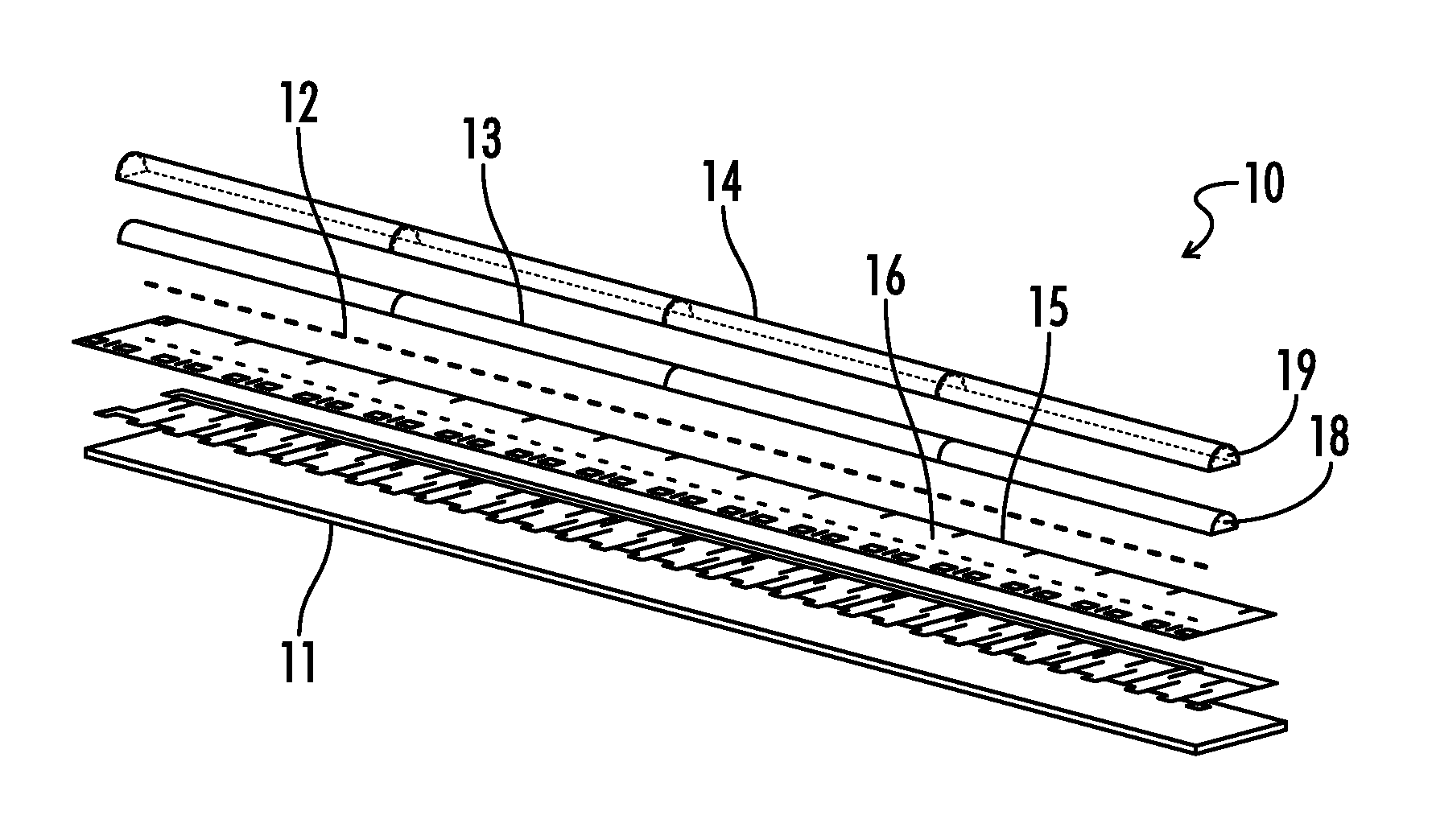
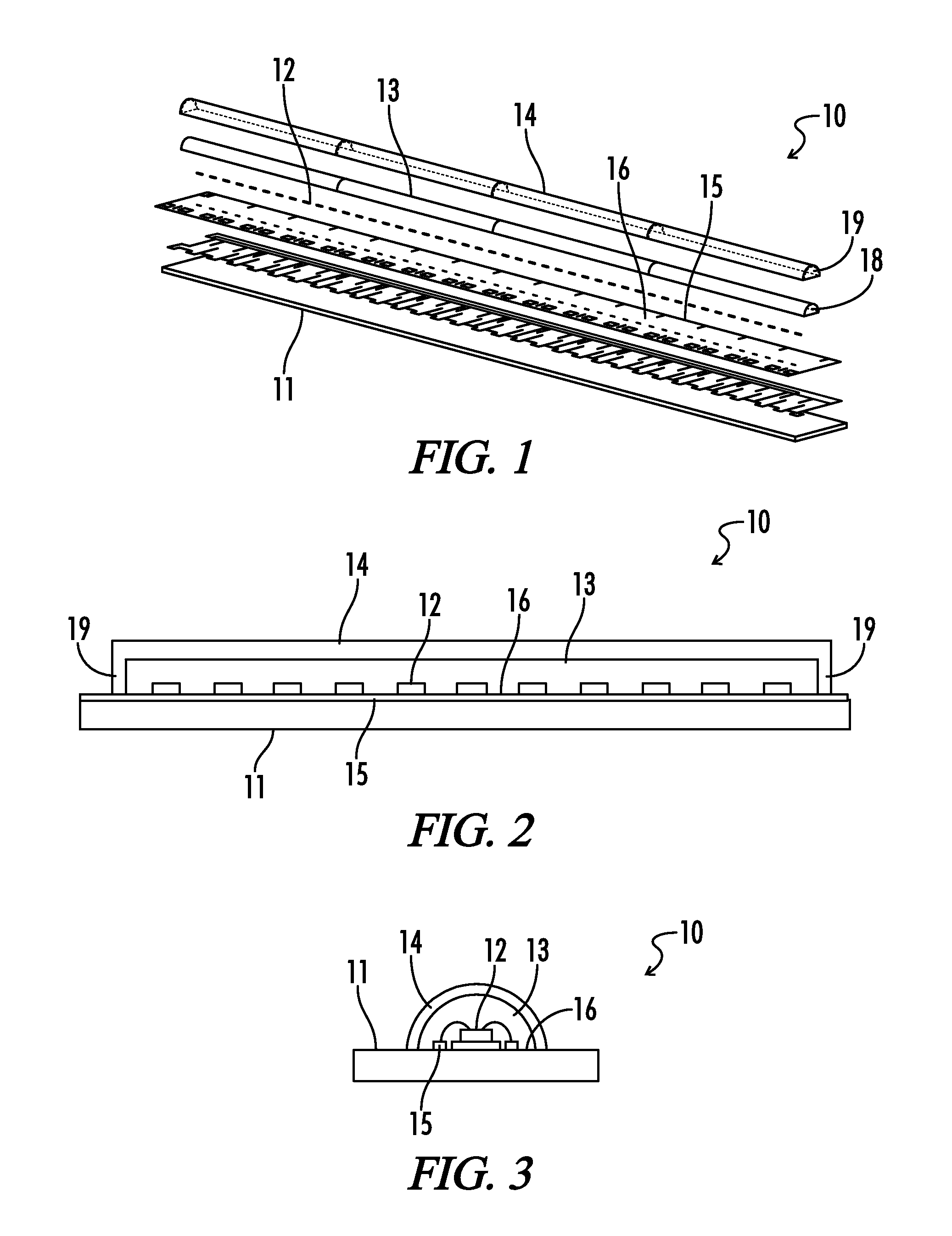
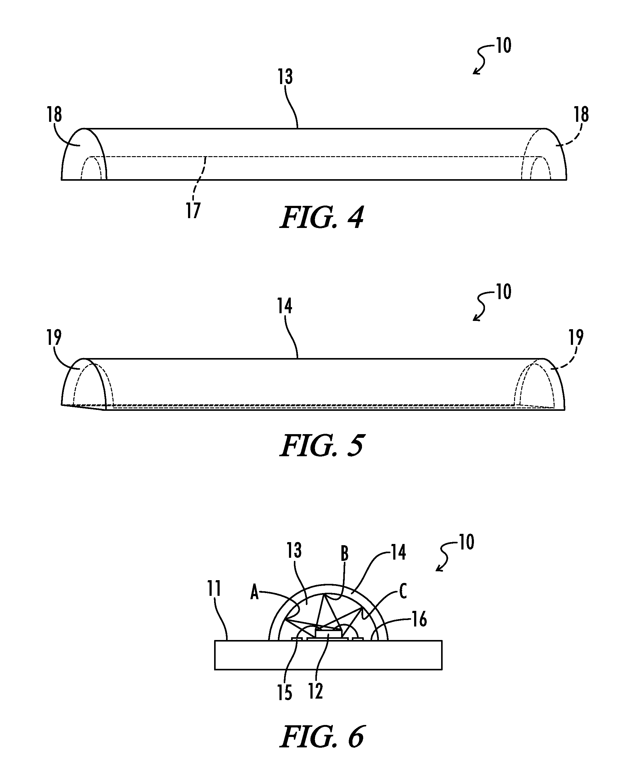
[0054]Referring generally to FIGS. 1-39, various embodiments may now be described herein of a lighting device that is effective to reduce luminance and color unevenness in associated light-emitting elements, and may further form an even and continuous light-emitting surface. Where the various figures may describe embodiments sharing various common elements and features with other embodiments, similar elements and features are given the same reference numerals and redundant des...


PUM


Abstract

A lighting device is provided in accordance with the present invention having reduced luminance and color unevenness. A plurality of solid-state light emitting elements are mounted on a base substrate. An optical member is further mounted on the substrate and arranged so as to cover light emitting surfaces of the light emitting elements, the optical member having a semicircular or semielliptical cross-sectional surface, and gutter-shaped in a longitudinal direction with respect to the substrate. A wavelength converting member covers the semicircular or semielliptical cross-sectional surface of the optical member, and is excitable by light from the solid-state light emitting elements to thereby emit wavelength-converted light. In various embodiments light diffusion members may be further distributed among the light emitting elements.

Description

[0001]A portion of the disclosure of this patent document contains material that is subject to copyright protection. The copyright owner has no objection to the reproduction of the patent document or the patent disclosure, as it appears in the U.S. Patent and Trademark Office patent file or records, but otherwise reserves all copyright rights whatsoever.CROSS-REFERENCES TO RELATED APPLICATIONS[0002]This application claims benefit of the following patent applications which is / are hereby incorporated by reference: Japanese Patent Application Publication No. 2010-153429 and Japanese Patent Application Publication No. 2010-190044.BACKGROUND OF THE INVENTION[0003]The present invention relates to a lighting device that uses a plurality of solid-state light emitting elements as a light source and as applied to an illumination fixture.[0004]Lighting devices are known in which a plurality of solid-state light emitting elements are mounted on a board. In general, the plurality of solid-state ...

Claims


Application Information

Patent Timeline
IPC IPC(8): F21V9/16
CPCH01L25/0753H01L33/50H01L33/60H01L2924/09701F21Y2115/10F21S4/28F21V9/30F21Y2103/10H01L2224/48091H01L2924/00F21V13/08F21V9/38
Inventor YOKOTANI, RYOJIKIBA, KEIJITANAKA, KENICHIRO
Owner MATSUSHITA ELECTRIC WORKS LTD
Why Eureka
Try Eureka