Transmitter apparatus, receiver apparatus, communication system, and communication method

a technology of transmitter and receiver, applied in the field of transmitter apparatus, receiver apparatus, communication system, communication method, can solve the problem of poor frequency spectrum utilization rate, and achieve the effect of efficient placement of reference signal

Active Publication Date: 2012-05-03
SHARP KK
View PDF2 Cites 37 Cited by
  • Summary
  • Abstract
  • Description
  • Claims
  • Application Information

AI Technical Summary

Benefits of technology

[0029]According to the present invention, it is possible in a communication system capable of non-cooperative communication and cooperative communication, to efficiently place the reference signal and to acquire appropriate feedback information.

Problems solved by technology

In this case, however, there is the problem of a poor rate of frequency spectrum utilization.

Method used


Image

  • Transmitter apparatus, receiver apparatus, communication system, and communication method
  • Transmitter apparatus, receiver apparatus, communication system, and communication method
  • Transmitter apparatus, receiver apparatus, communication system, and communication method

Examples


first embodiment

[0056]The first embodiment of the present invention will be described below, with references made to drawings.

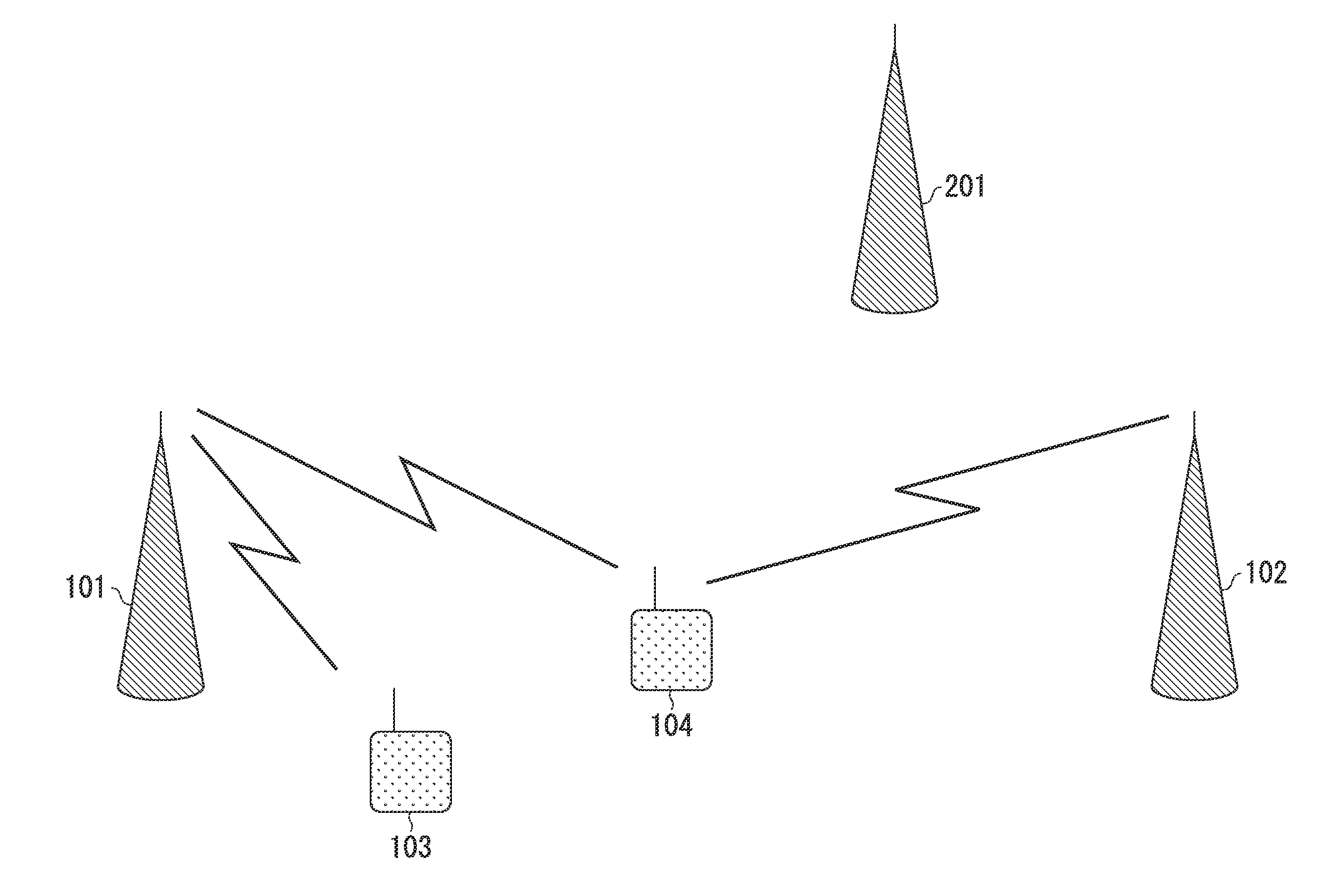
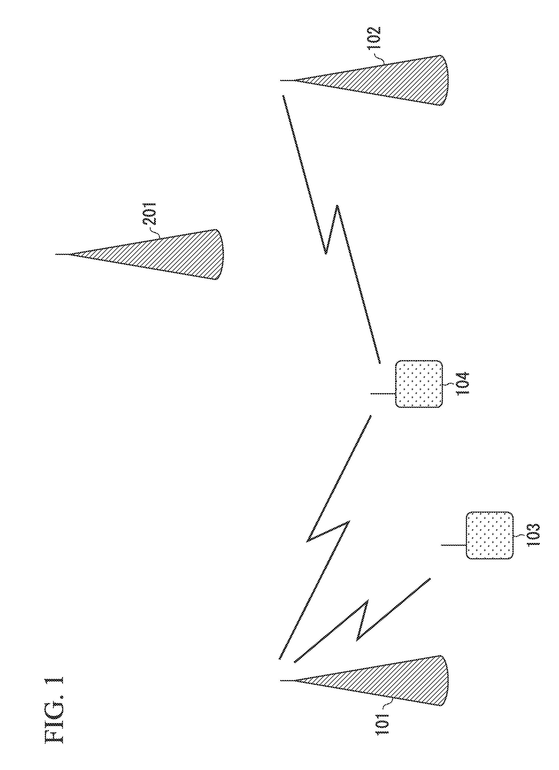
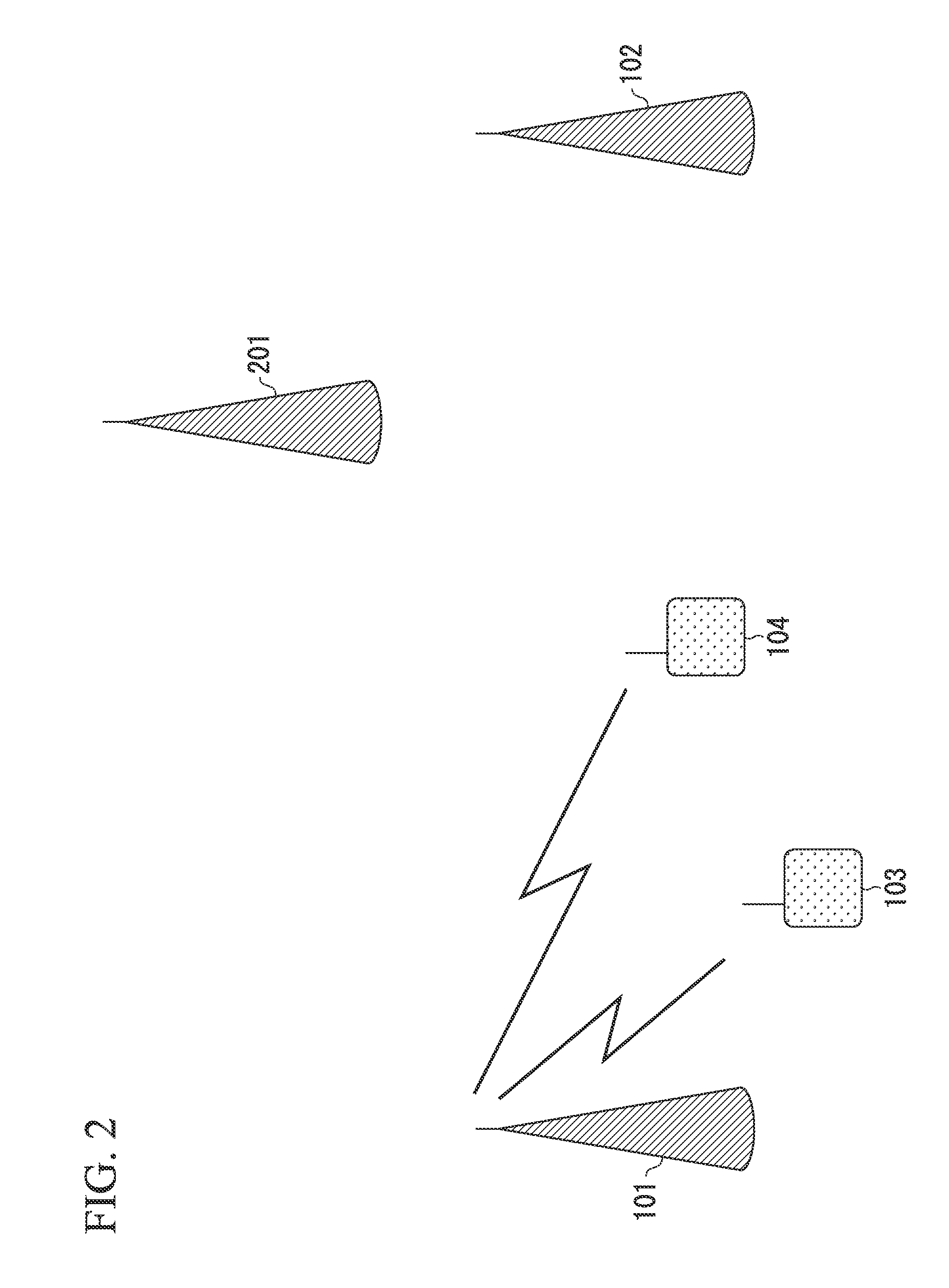
[0057]FIG. 1 is a schematic drawing showing the configuration of a communication system according to the first embodiment of the present invention. The communication system of FIG. 1 includes base stations (transmitter apparatuses, base station apparatuses, eNodeB, eNB, cells, uplink receiver apparatuses) 101 and 102, which constituted each of the cells, and terminal devices (receiver apparatuses, UEs, uplink transmitter apparatuses) 103 and 104. The base station 101 and the terminal device 103 perform MIMO communication, which is non-CoMP (or SISO (single-input, single-output) communication and transmission diversity (TxD)).

[0058]The base station 101 and the base station 102 perform communication with the terminal device 104 by CoMP communication (cooperative communication). That is, at least both MIMO communication and CoMP communication are performed by the base station 1...

second embodiment

[0123]In the first embodiment, the description is for the case in which the subframes in which CoMP reference signals are placed are synchronized (placed at the same time) between cells capable of CoMP. In the second embodiment of the present invention, the case in which the CoMP reference signals are placed in different subframes between cells capable of CoMP will be described.

[0124]Because the base station and terminal device configurations in the second embodiment are the same as those of the base station (FIG. 7) and the terminal device (FIG. 8) in the first embodiment, their descriptions will be omitted herein.

[0125]The present embodiment will be described below, with references made to the drawings.

[0126]FIG. 9A to FIG. 9C are drawings showing examples of the configuration of the reference signal that are referenced by the terminal device that performs CoMP. In FIG. 9A to FIG. 9C, the horizontal axis represents time and the vertical axis represents frequency. In the present em...

third embodiment

[0137]In the first embodiment, the description is for the case in which notification is made of the position of the first reference signal when transitioning to the MIMO mode, and notification is made of the position of the second reference signal when transitioning to the CoMP mode. In the third embodiment, the description will be for the case in which the position of the first reference signal is notified to the terminal device from the base station, and notification is made of the position of the second reference signal to the terminal device from the base station when transitioning to the CoMP mode.

[0138]Because the configurations of the base station and the terminal device in the third embodiment are the same as the base station (FIG. 7) and the terminal device (FIG. 8) in the first embodiment, detailed descriptions thereof will be omitted herein.

[0139]The present embodiment is described below, with references made to FIG. 11. FIG. 11 is a sequence diagram showing an example of...


PUM


Abstract

A transmitter apparatus includes a reference signal transmitting unit that transmits a both of a first reference signal and a second reference signal differing from the first reference signal to a first receiver apparatus performing non-cooperative communication and to a second receiver apparatus performing cooperative communication, respectively. In addition, the transmitter apparatus includes a notifying unit that instructs the first receiver apparatus to measure the first reference signal and that instructs the second receiver apparatus to measure the second reference signal.

Description

TECHNICAL FIELD[0001]The present invention relates to a transmitter apparatus, a receiver apparatus, a communication system, and a communication method.[0002]The present application claims priority based on the patent application 2009-142873, filed on Jun. 16, 2009 in Japan, the content of which is incorporated herein by reference.BACKGROUND ART[0003]Known mobile wireless communication systems include those such as WCDMA (Wideband Code-Division Multiple Access), LTE (Long Term Evolution), LTE-A (LTE-Advanced) and WiMAX (Worldwide Interoperability for Microwave Access), in accordance with 3GPP (Third Generation Partnership Project). In these mobile wireless communication systems, an area that is covered by a base station (base station apparatus, transmitting station, transmitter apparatus, eNodeB) or a transmitting station that is in accordance with a base station has a cellular configuration in which a plurality of cells are disposed, thereby enabling an expansion of the communicati...

Claims


Application Information

Patent Timeline
Patent Type & Authority Applications(United States)
IPC IPC(8): H04B17/00H04W28/16H04W28/18H04W72/04H04W72/12
CPCH04B7/024H04L5/0057H04B7/063H04L1/0026H04L1/0028H04L5/0007H04L5/0023H04L5/0035H04L5/0048H04L2001/0092H04W72/0406H04L5/0042H04L5/0094H04L5/0073H04B7/0417H04W72/20H04W88/02H04W88/08
Inventor NOGAMI, TOSHIZOSHIMEZAWA, KAZUYUKIYAMADA, SHOHEIOH, WAHOH
Owner SHARP KK
Why Eureka
Try Eureka