Rolling bearing arrangement

a bearing arrangement and rolling bearing technology, applied in the direction of bearings, bearing components, rotary bearings, etc., can solve the problems of deteriorating bearing ring bearing capacity, affecting their material requirement and weight, etc., to achieve the reduction of the design space of the transmission, the effect of reducing weight and keeping the material requirement at a lower level

Inactive Publication Date: 2012-05-03
SCHAEFFLER TECH AG & CO KG
View PDF2 Cites 14 Cited by
  • Summary
  • Abstract
  • Description
  • Claims
  • Application Information

AI Technical Summary

Benefits of technology

[0018]The advantage of the invention resides particularly in the fact that such an arrangement does not require more radial design space than a prior art arrangement without lash compensation element and can thus be used in existing constructions, for example, in power take-off gears of automotive vehicles. Compared to prior art arrangements in which TCE's are used, the bearing rings are not weakened because it is no longer necessary to provide a valley channel in the dimensions of the TCE for accommodating the lash compensation element, but at the most, a recess

Problems solved by technology

Such a valley channel can be made in a bearing ring only if the bearing ring has adequate axial and radial dimensions: if not, the bearing capacity of the bearing ring is deteriorated because an insufficient quantity of material remains behind in the regions next to the raceways of the

Method used


Image

  • Rolling bearing arrangement
  • Rolling bearing arrangement

Examples


Embodiment Construction

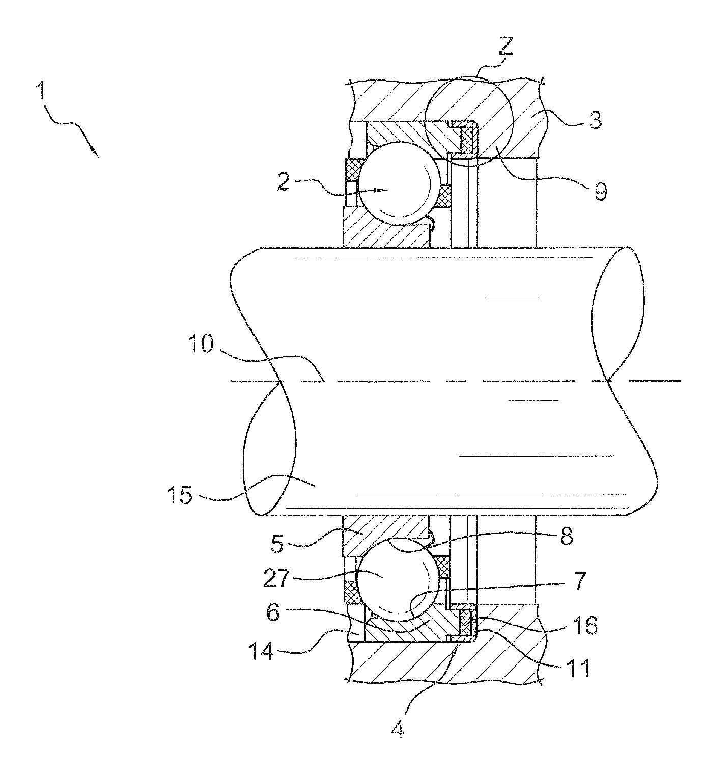
[0024]FIG. 1 shows a rolling bearing arrangement1 comprising at least one angular contact rolling bearing 2 in a housing 3 and a lash compensation element 4 in the form of a TCE 16 in a longitudinal section along the axis of rotation 10. The TCE 16 is made of a material that has a different thermal expansion coefficient from the materials of which the housing 3 and the angular contact bearing 2 as also a shaft 15 are made. FIG. 1a shows the detail Z with a longitudinal section through the junction of the TCE 16 and a bearing ring 6 of the angular contact rolling bearing 2.

[0025]The angular contact rolling bearing 2 comprises an inner bearing ring 5 and an outer bearing ring 6. Rolling elements 27 in the form of balls are arranged radially between the bearing rings 5 and 6 and are supported on raceways 7 and 8. The TCE 16 is supported in one axial direction on an axial support 9 of the housing 3 and can be biased or is biased in the other axial direction against the outer bearing rin...


PUM


Abstract

A rolling bearing arrangement, which has at least one angular contact rolling bearing arranged within a housing and at least one lash compensation element that is supported axially in one direction on the housing and is capable of being biased against a bearing ring of the angular contact rolling bearing with the bearing ring being axially movable relative to the housing, and a U-shaped ring which has two radially opposing legs directed in an axial direction. The U-shaped ring rendering the lash compensation element radially immovable by positive engagement while being guided on the bearing ring of the angular contact rolling bearing for axial displacement relative to the bearing ring, and the axial section of the bearing ring projecting axially between the legs of the ring profile.

Description

CROSS-REFERENCE TO RELATED APPLICATION[0001]This application claims the priority of U.S. 61 / 407,123 filed on Oct. 27, 2010, which is incorporated herein by reference.FIELD OF THE INVENTION[0002]The invention concerns a rolling bearing arrangement, which has at least one angular contact rolling bearing within a housing and at least one lash compensation element that is supported axially in one direction on the housing and is capable of being biased against a bearing ring of the angular contact rolling bearing with the bearing ring being axially movable relative to the housing.BACKGROUND OF THE INVENTION[0003]In rolling bearing arrangements comprising angular contact bearings for the mounting of shafts in vehicle transmissions, as a rule two of the angular contact bearings are biased lash-free against each other. In angular contact rolling bearing arrangements, lash-free biasing means that the angular contact bearings are biased both in radial and in axial direction and that at least ...

Claims


Application Information

Patent Timeline
IPC IPC(8): F16C25/08F16C33/58F16C25/06
CPCF16C19/163F16C25/083F16C33/586
Inventor DOERRFUSS, FLORIANBIERMANN, THORSTENWIESINGER, FRITZ
Owner SCHAEFFLER TECH AG & CO KG
Why Eureka
Try Eureka