Load adaptive EMI reduction scheme for switching mode power supply

a power supply and switching mode technology, applied in the field of frequency jittering generators, can solve the problems of noise problems, communication device problems, relative high operation switching frequency, etc., and achieve the effect of keeping the low level of switching power supply and low cos

Active Publication Date: 2010-10-28
FREMONT MICRO DEVICES CORP
View PDF6 Cites 21 Cited by
  • Summary
  • Abstract
  • Description
  • Claims
  • Application Information

AI Technical Summary

Benefits of technology

[0006]The objective of this invention is to overcome said problem of the prior art and provide a new frequency jittering scheme that can apply low cost simple EMI filter for EMI reduction but also can keep low level of switching power supply output noise floor at light load conditions.

Problems solved by technology

A well-known issue with using switching mode power supply is its relative high operation switching frequency.
This high frequency signal is coupled back into the AC mains input and becomes a component of the AC mains that can cause noise problems for those devices connected to the same AC mains power line.
In addition, the high frequency signals are also radiated by the power supply as electromagnetic waves to create Electromagnetic Interference (EMI) that can also cause problems for communications devices in the neighborhood of the power supply.
The merit of this frequency jittering scheme is the elimination of an expensive and bulky EMI filter but its draw back is the rise of average noise floor which is not acceptable in certain application like in high fidelity audio system.
For a high fidelity audio system, it can tolerate higher averaging output noise floor generated from switching power supply at high sound volume but becomes very noise sensitive at light sound volume.

Method used


Image

  • Load adaptive EMI reduction scheme for switching mode power supply
  • Load adaptive EMI reduction scheme for switching mode power supply
  • Load adaptive EMI reduction scheme for switching mode power supply

Examples


Embodiment Construction

[0074]These and other advantage, aspect and novel features of the present invention, as well as details of an illustrated embodiment thereof, will be more fully understand from the following description and drawings. While various embodiments of the present invention has been presented by way of example only, and not limitation.

[0075]The main concept of the present invention is to have wider frequency swing at heavy load to take advantage of prior art scheme by using small low cost EMI filter but have narrow frequency swing at light load to maintain low level of noise floor.

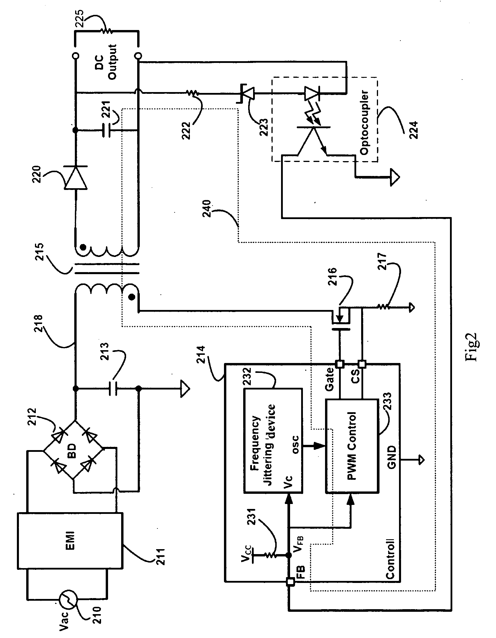
[0076]FIG. 2 is a schematic illustrating a power supply with a new frequency jittering scheme with load adaptive frequency swing. Said power supply consists of an input circuit formed by EMI filter 211, Bridge Rectifier 212 and Filter Capacitor 213; Transformer 215, Control 214, Power Switch 216, Current Sense Resistor 217, and an output circuit formed by Output Diode 220, Output Capacitor 221, Output Voltage Sen...


PUM


Abstract

The present invention relates to a frequency jittering device and method, and a switching power supply employing such frequency jittering device. Said method comprises: S1 generating a variable logic number; S2 generating a delay signal; S3 generating a PWM control signal according to the variable logic number and the delay signal; S4 generating an output signal according to the PWM control signal; and S5 generating a clock signal with variable frequency according to the output signal; wherein, the clock signal is fed back to update the variable logic number, and a jittering clock signal modified in each clock cycle is produced. The benefit of the present invention is not only can apply small low cost EMI filter but also can keep the noise floor level low enough at light load condition.

Description

REFERENCE TO RELATED PATENT DOCUMENT[0001]U.S. Pat. No. 6,249,876, published on Jun. 19, 2001, and entitled “Frequency Jittering Control for Varying the Switching Frequency of a Power Supply” is cited herein in its entirety by reference for all purpose.FIELD OF THE INVENTION[0002]The present invention relates to a frequency jittering generator; and more specific, to a Frequency Jittering device that utilizes current or voltage control delay time circuit and digital control pulse width generator for varying both switching frequency and percentage of modulation swing period.BACKGROUND OF THE INVENTION[0003]A well-known issue with using switching mode power supply is its relative high operation switching frequency. This high frequency signal is coupled back into the AC mains input and becomes a component of the AC mains that can cause noise problems for those devices connected to the same AC mains power line. In addition, the high frequency signals are also radiated by the power supply...

Claims


Application Information

Patent Timeline
Patent Type & Authority Applications(United States)
IPC IPC(8): G06F1/04
CPCG06F1/08H02M1/44H04R3/00H03K3/84H03K7/08H02M3/33507
Inventor KU, MATTHEW MAN HO
Owner FREMONT MICRO DEVICES CORP
Why Eureka
Try Eureka