Image photographing device having function for compensating hand vibration

a photographing device and hand vibration technology, applied in the field of image photographing devices having a function for compensating hand vibration, can solve the problems of deteriorating image quality and obtaining blur photographs, and deformation of compensation performance, so as to prevent deformation of suspension wires

Active Publication Date: 2012-05-03
SAMSUNG ELECTRO MECHANICS CO LTD
View PDF1 Cites 70 Cited by
  • Summary
  • Abstract
  • Description
  • Claims
  • Application Information

AI Technical Summary

Benefits of technology

[0018]An object of the present invention is to provide an image photographing device having a function for compensating hand vibration capable of preventing deformations of a suspension wi

Problems solved by technology

As the camera module configured as described above is implemented as high pixels and high functions, the size of a pixel is small and the number of components through which light passes are increased, such that the light receiving sensitivity photographed by the image sensor may be sensitive and the focus of an image photographed by the image sensor become deviated even in slight hand vibrations at the instant when the shutter of the camera or the mobile device is operated, thereby deteriorating the image quality and obtaining blur photographs.
In this case, when the lens moves along the biaxial guide, there are problems in that the compensation performance may be degraded due to the friction between the biaxial guide and the lens and noise or foreign materials may occur due to the friction with other component members at the time of driving the biaxial guide and the lens or the biaxial guide.
However, when the external im

Method used


Image

  • Image photographing device having function for compensating hand vibration
  • Image photographing device having function for compensating hand vibration
  • Image photographing device having function for compensating hand vibration

Examples


Embodiment Construction

[0036]The acting effects and technical configuration with respect to the above objects of an image photographing device having a function for compensating hand vibration according to the present invention will be clearly understood by the following description in which exemplary embodiments of the present invention are described with reference to the accompanying drawings.

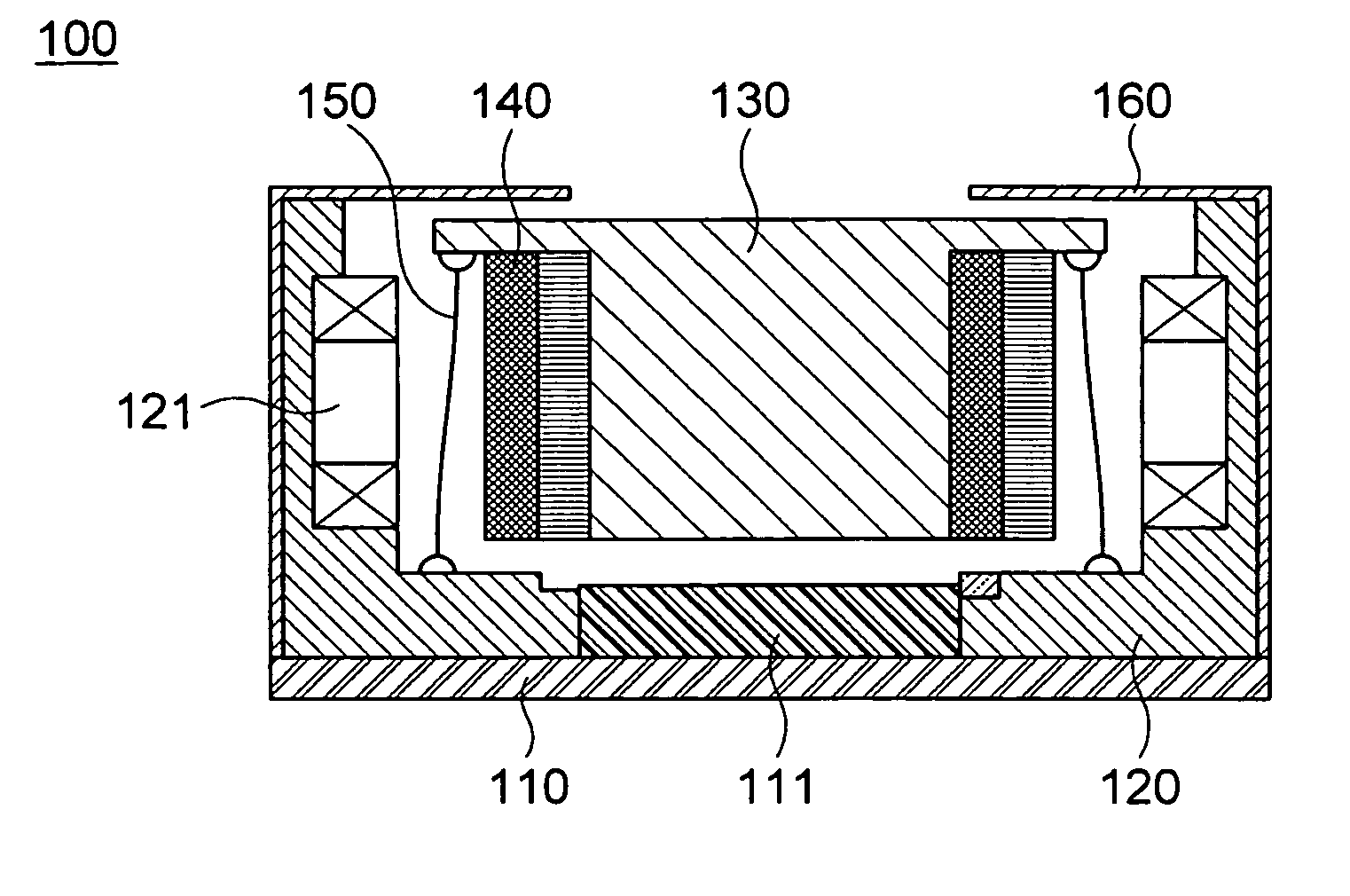
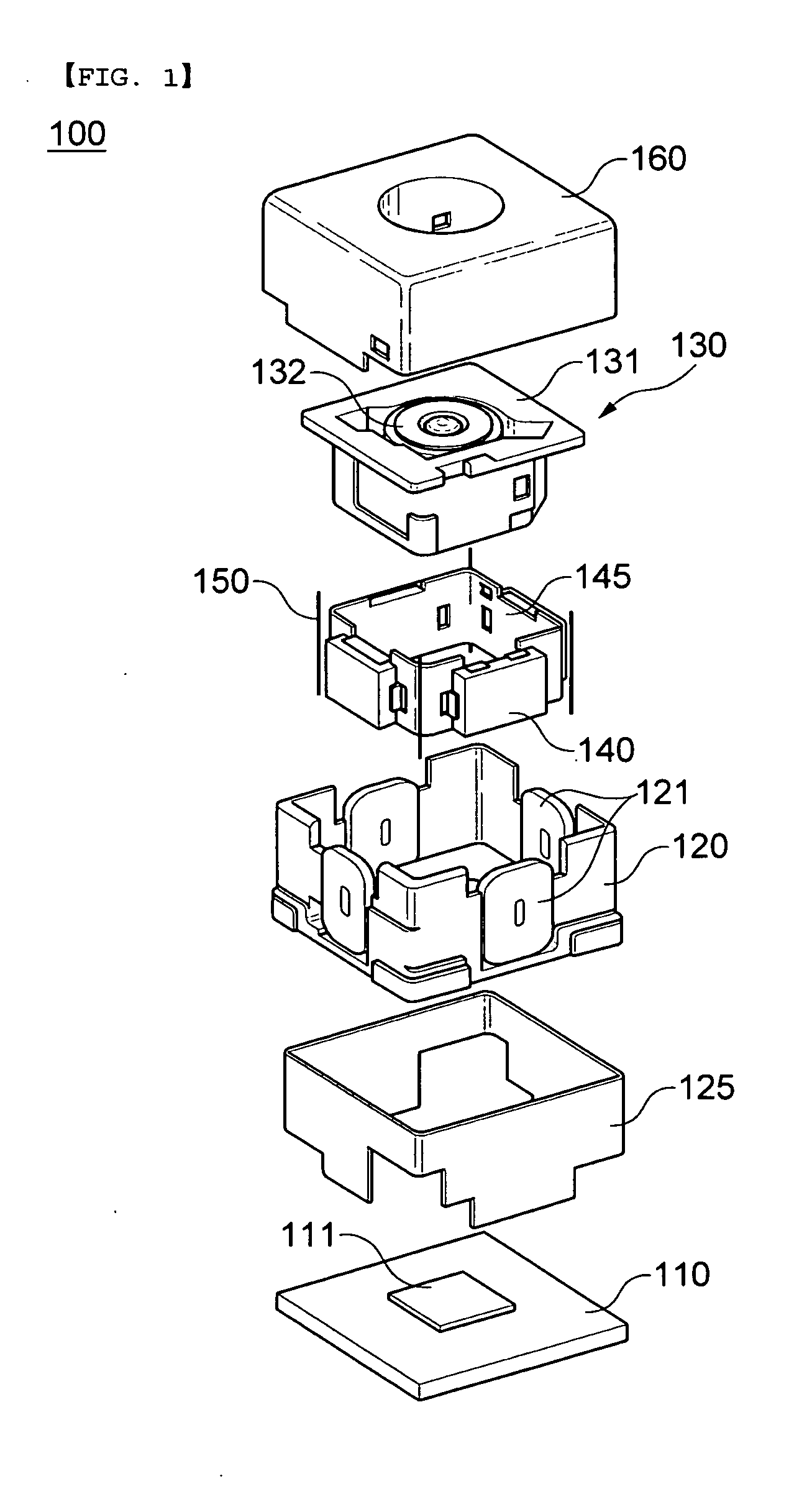
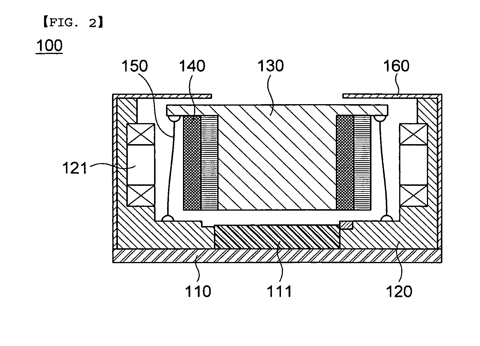
[0037]First, FIG. 1 is an exploded perspective view of an image photographing device having a function for compensating hand vibration according to the present invention and FIG. 2 is a cross-sectional view of an image photographing device having a function for compensating hand vibration of the present invention.

[0038]As shown, an image photographing device 100 having a function for compensating hand vibration according to the present invention may be configured to include a substrate 110 on which an image sensor 111 is mounted, a housing 120 mounted on the substrate 110, an optical unit 130 and a magnet 140 inser...


PUM


Abstract

Disclosed herein is an image photographing device having a function for compensating hand vibration. The image photographing device having a function for compensating hand vibration includes: an optical unit; a magnet combined with an outer peripheral surface of the optical unit; a housing inserted with the optical unit and the magnet and having coils disposed at a position corresponding to the magnet; suspension wires arranged at four corners of the optical unit, having the upper end portions and the lower end portions each combined with the optical unit and the housing to support the optical unit in a state floated from the bottom surface of the housing, and having a predetermined bending part formed at any point; a flexible printed circuit board surrounding the outer peripheral surface of the housing and applying current to the coils; and a substrate having the image sensor mounted on the top surface thereof and combined with the lower portion of the housing.

Description

CROSS REFERENCE(S) TO RELATED APPLICATIONS[0001]This application claims the benefit under 35 U.S.C. Section 119 of Korean Patent Application Serial No. 10-2010-0108806, entitled “Image Photographing Device Having Function For Compensating Hand Vibration” filed on Nov. 3, 2010, which is hereby incorporated by reference in its entirety into this application.BACKGROUND OF THE INVENTION[0002]1. Technical Field[0003]The present invention relates to an image photographing device having a function for compensating hand vibration, and more particularly, to an image photographing device having a function for compensating hand vibration capable of minimizing deformations of a suspension wire caused due to an external impact by changing a shape of the suspension wire and a supporting structure supporting an optical unit.[0004]2. Description of the Related Art[0005]Recently, the use of a subminiature camera module for a mobile device has been increasingly expanded for mobile devices such as mob...

Claims


Application Information

Patent Timeline
IPC IPC(8): G02B27/64G03B17/00G03B5/00G03B17/12G03B30/00
CPCG03B5/02G03B2205/0015G03B2205/0069H04N5/2257H04N23/57G02B27/646
Inventor LIM, SOO CHEOLLEE, JUNG SEOKKANG, BYUNG WOOON, SANG MINYOON, YOUNG BOKKANG, SEONG HO
Owner SAMSUNG ELECTRO MECHANICS CO LTD
Why Eureka
Try Eureka