Drilling head with axial vibrations

a drilling head and axial vibration technology, applied in the direction of drilling tools, boring/drilling equipment, turning apparatus, etc., can solve the problems of affecting the quality of the surface of the hole, the inability to generate movement, and the chip to break up, so as to relieve the shim

Active Publication Date: 2012-05-03
ARTS +1
View PDF9 Cites 40 Cited by
  • Summary
  • Abstract
  • Description
  • Claims
  • Application Information

AI Technical Summary

Benefits of technology

[0015]As in the previous embodiment, the combined length of the generator and of the shim in relation to the free length of the external sleeve and to its elastic property in the axial direction allows the preload on the generator to be adjusted. The piezoelectric generator is protected against torsion moments both by the external sleeve and by the aforementioned flexible element which together relieve the shim from the need to isolate the tool holder from the generator torsionally; this measure makes it possible to react radial load that cannot be reacted by the sliding pivot connection when this connection has play, even if this play is small. It is possible to employ another flat element for suspending the tool holder from the mount in parallel with the first one and therefore also with the external sleeve, this other flat element being situated in the region of the pressing shim, which has reliefs p

Problems solved by technology

A drilling machine has the disadvantage of producing long chips which present various problems in the drilling operation because they are difficult to move quickly away from the work zone and may impair the quality of the surface of the hole produced.
One remedy to this disadvantage is to cause these chips to break up by varyi

Method used


Image

  • Drilling head with axial vibrations
  • Drilling head with axial vibrations
  • Drilling head with axial vibrations

Examples


Embodiment Construction

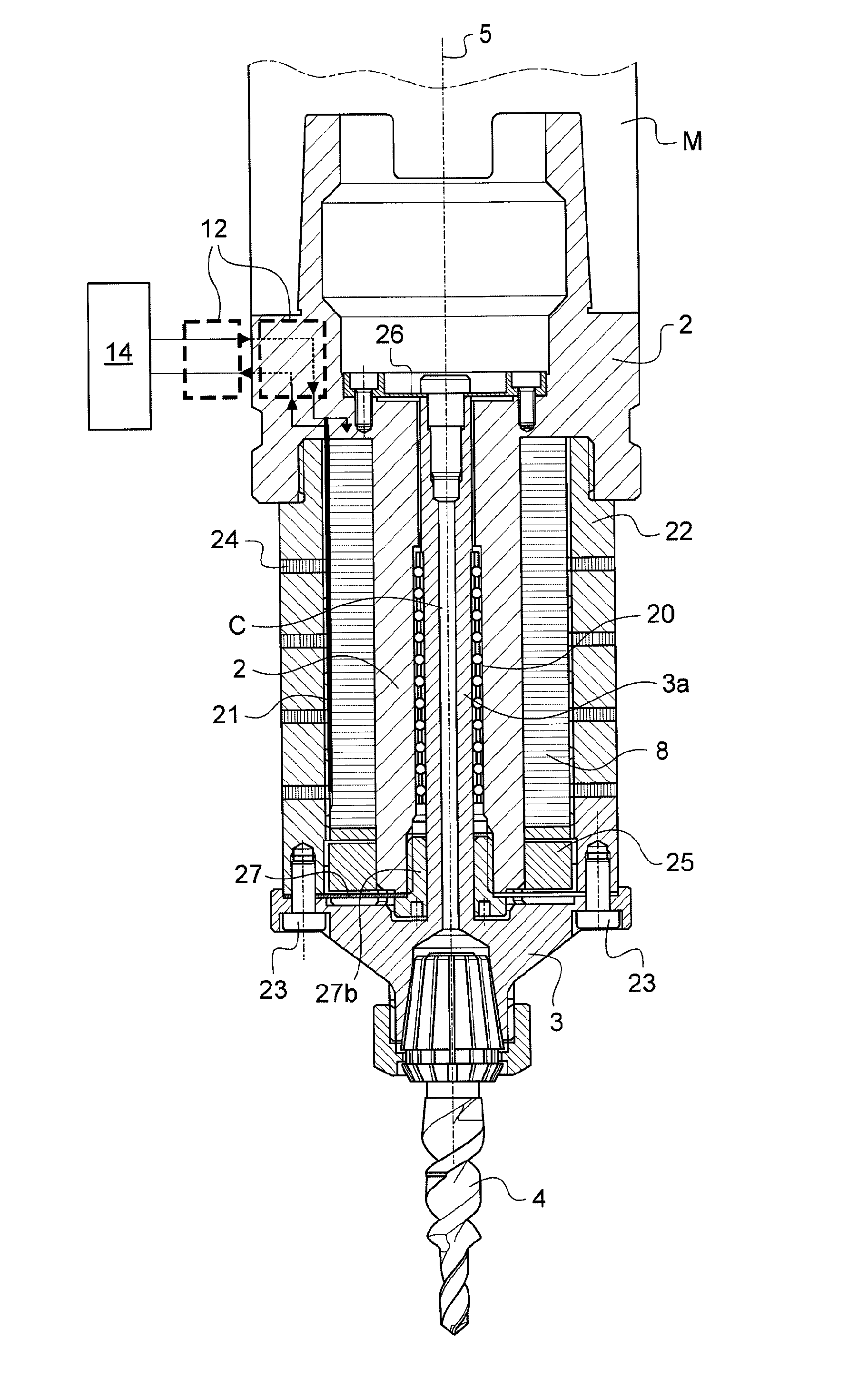
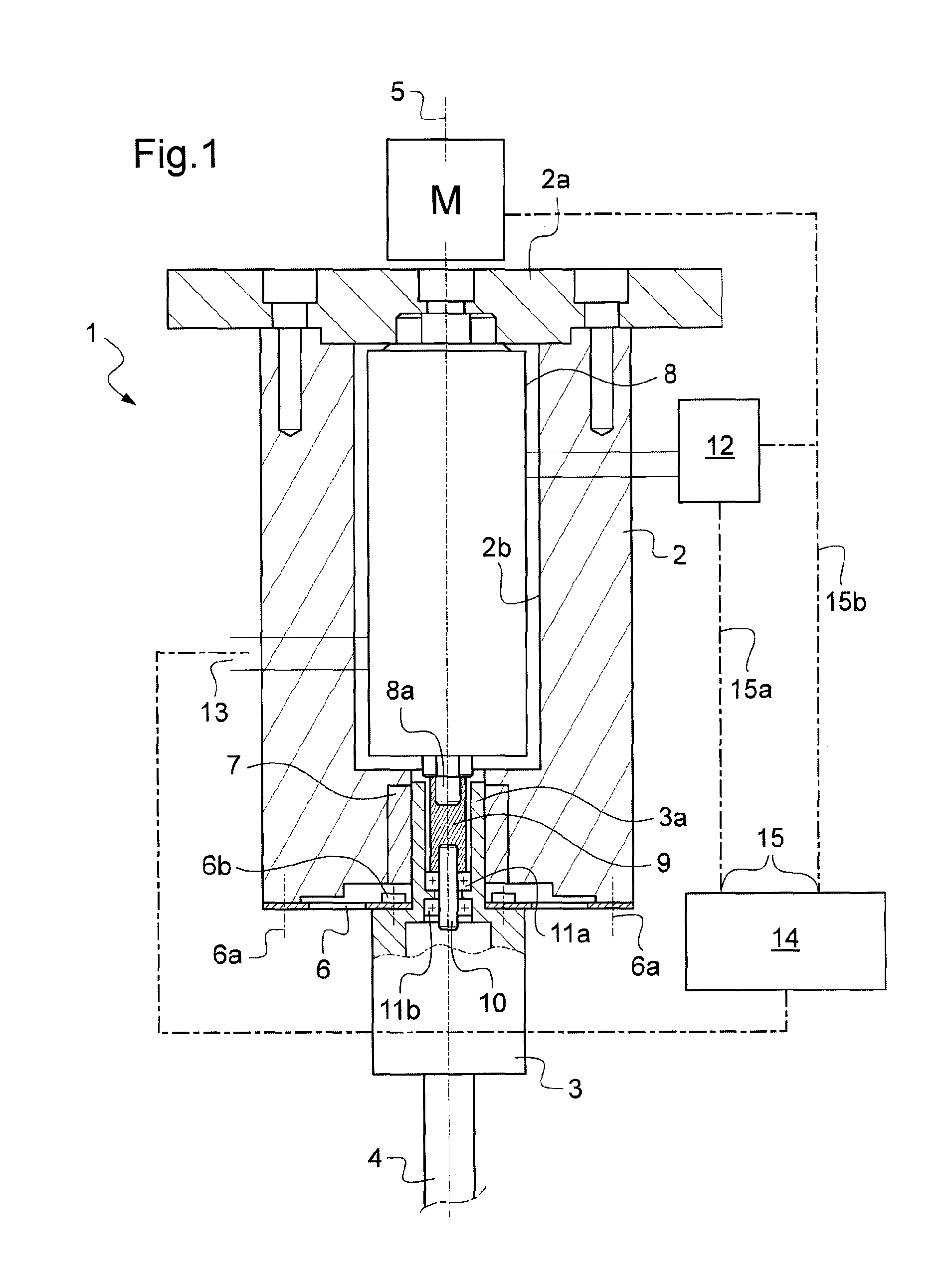
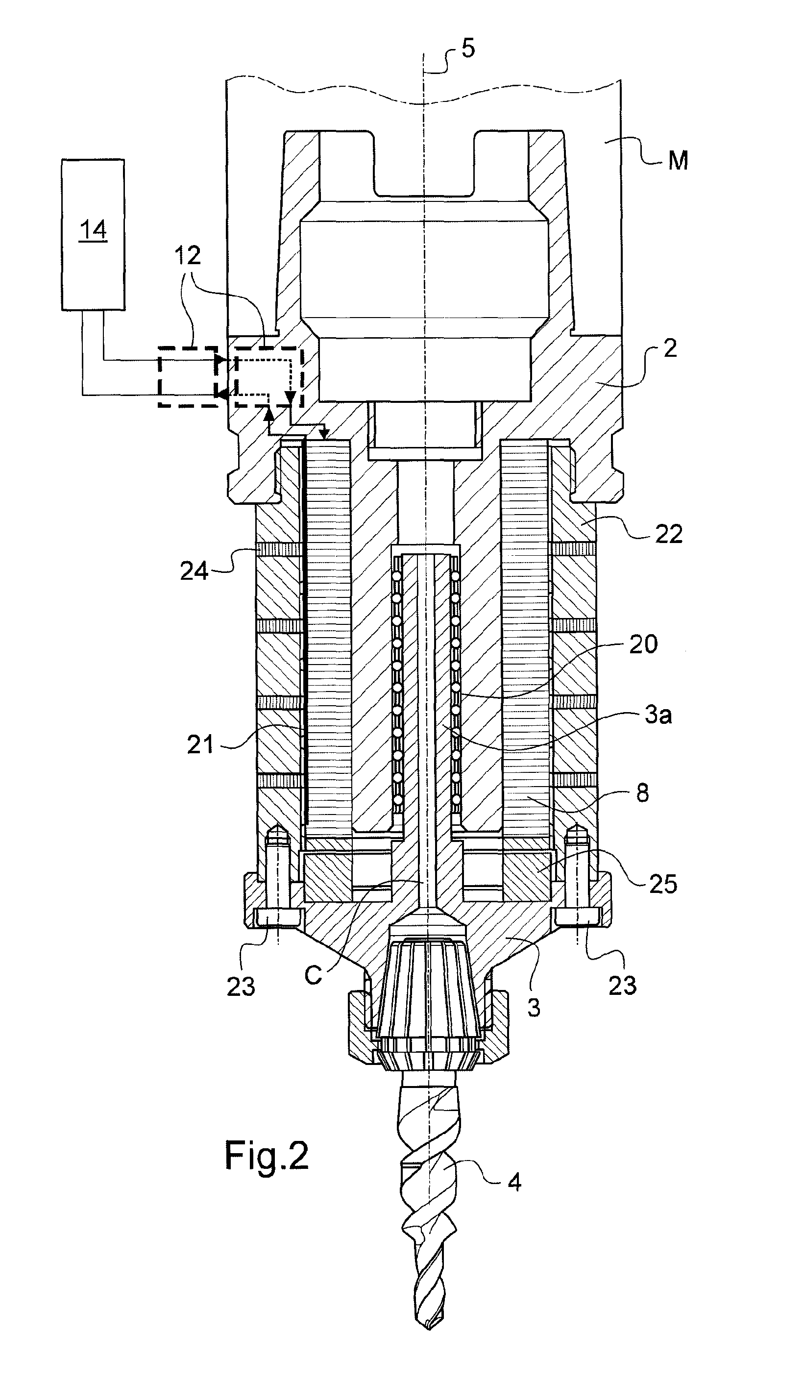
[0025]In FIG. 1, the drilling head depicted as 1 comprises a mount 2 and a tool holder 3 to keep a drill bit 4 coaxial with an axis 5 of rotation of the mount 2.

[0026]Via its end 2a, the mount is coupled to a drive motor M depicted schematically and the axis of rotation of which is coaxial with the axis 5 which is also the longitudinal axis of the mount 2.

[0027]The tool holder 3 is fixed to the mount 2 by a washer 6 which has the property of transmitting a torque between the mount and the tool holder and which is elastically deformable in the direction of the axis 5. One example of such a washer is described in document EP 994 758. This washer 6 is fixed by peripheral screws 6a to the mount 2 while the tool holder 3 is fixed to the washer 6 by central screws 6b. The tool holder 3 has a central part 3a which is guided with axial sliding in a bearing 7 of the mount.

[0028]The mount 2 is hollow and its central recess 2b contains a piezoelectric actuator 8 of which the oscillations, whic...


PUM

PropertyMeasurementUnit
Forceaaaaaaaaaa
Bending strengthaaaaaaaaaa
Stiffnessaaaaaaaaaa

Abstract

A drilling head (1) with an axial oscillation generator, includes a mounting (2) for coupling the head to a motor for rotating the mounting about an axis, the mounting (2) having a longitudinal axis (5) coinciding with the axis of rotation of the motor, a tool holder (3), an elastically deformable element (6) for retaining the tool holder (3) in the mounting (2) and an element (7) for guiding the tool holder (3) in the mounting (2) along the longitudinal axis (5) of the mounting, wherein the mounting of the drilling head includes a controlled generator (8) of reciprocating movements in the direction of the aforementioned axis (5) positioned between the mounting (2) and the tool holder, the tool holder and the generator being connected by a longitudinal coupling member (9) suitable for damping the impacts withstood by the tool holder while enabling the transmission of the reciprocating movements.

Description

[0001]The present invention relates to a drilling head fitted with a generator of axial oscillations (vibrations).BACKGROUND OF THE INVENTION[0002]A drilling machine has the disadvantage of producing long chips which present various problems in the drilling operation because they are difficult to move quickly away from the work zone and may impair the quality of the surface of the hole produced.[0003]One remedy to this disadvantage is to cause these chips to break up by varying their thickness and by repeatedly interrupting the cutting operation. This is achieved by applying to the cutting tool, which is generally a drill bit, an axial vibration which makes the feedrate (the rate of penetration into the material) cyclically variable and therefore makes the thickness of the chip variable, with amplitudes and frequencies that cause the chips to break up.[0004]At the same time, there are drilling operations in which it is beneficial to vibrate the tool only at certain times (when drill...

Claims


Application Information

Patent Timeline
IPC IPC(8): B23B37/00B23B47/34
CPCB23B29/125B23B37/00B23B47/34B23B2228/36Y10T408/23B23B2260/066B23B2260/108Y10S82/904Y10S408/70B23B2260/008
Inventor MORARU, GEORGEVERON, PHILIPPERABATE, PATRICE
Owner ARTS
Why Eureka
Try Eureka