Eureka AIR delivers breakthrough ideas for toughest innovation challenges, trusted by R&D personnel around the world.

Mold having push-out structure

Inactive Publication Date: 2012-05-03
CHENG UEI PRECISION IND CO LTD
View PDF24 Cites 5 Cited by
  • Summary
  • Abstract
  • Description
  • Claims
  • Application Information

AI Technical Summary

Benefits of technology

[0008]As aforementioned, as the mold having the push-out structure the present invention is closed, it can prevent the moving half to interfere the push-out element and to impact the fixed half because the return pin can drive the push-out structure with the elastic element. Accordingly, the lifetimes of the push-out structure and the parting planes of the mold can be extended to reduce the maintenance cost. Noise caused by closing mold with high speed can be prevented to raise the stability and the productivity of manufacture.

Problems solved by technology

However, as the aforesaid mold having the push-out structure is closed, the moving half will be closed and interfere the push-out structure before the push-out structure is not in position completely.
Consequently, the parting planes of the push-out elements and the moving half can be crashed and damaged.
Besides, there is loud noise caused because the moving half is crashing the fixed half with high speed at moment of completely closed.
The lifetime of the mold will be effected and maintenance cost will increase.

Method used


Image

  • Mold having push-out structure
  • Mold having push-out structure
  • Mold having push-out structure

Examples


Embodiment Construction

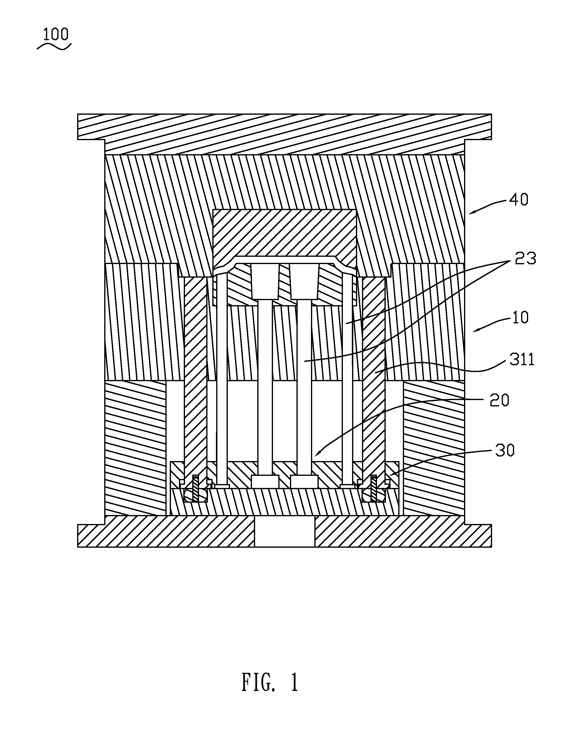
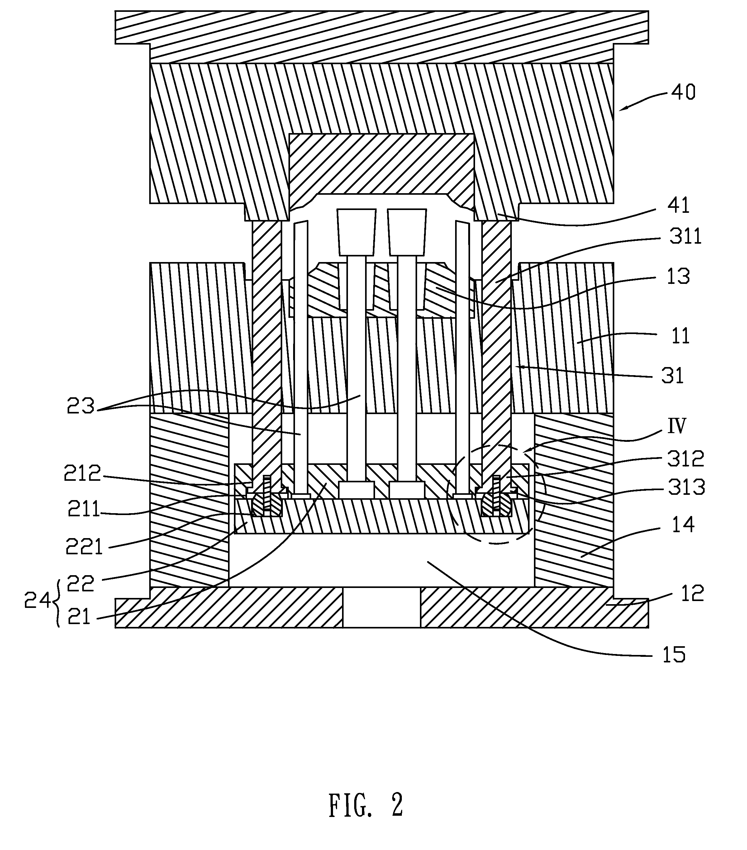
[0013]Please refer to FIG. 1 and FIG. 2. The mold 100 of the present invention comprises a moving half 40, a fixed half 10, a push-out structure 20 and a return protection system 30. The push-out structure 20 is installed on the fixed half 10. The return protection system 30 is installed on the push-out structure 20.

[0014]The moving half 40 has a pressing part 41. The fixed half 10 comprises a cavity fixing plate 11, a lower fixing plate 12, a pair of spacing blocks 14 positioned between the cavity fixing plate 11 and the lower fixing plate 12. A fixed half cavity 13 is fixed on the cavity fixing plate 11. An accepting space 15 is surrounded by the cavity fixing plate 11, the lower fixing plate 12 and the two spacing blocks 14 and formed thereby.

[0015]The push-out structure 20 comprises push-out elements 23 and a push-out plate 24 fox fixing the push-out elements 23. The push-out plate 24 comprises an upper push-out plate 21 and a lower push-out plate 22 fixed with each other. The p...


PUM

PropertyMeasurementUnit
Speedaaaaaaaaaa
Stabilityaaaaaaaaaa

Abstract

Disclosed is a mold, comprising a fixed half, a moving half, a push-out structure and a return protection system. The moving half has a pressing part. The push-out structure is installed on the fixed half. The push-out structure comprises a push-out element and a push-out plate. The return protection system comprises a return pin and an elastic element, installed between the return pin and the push-out element. The pressing part can press against the return pin. With the elastic element, the return pin can drive the push-out structure. It can prevent the moving half to interfere the push-out element and to impact the fixed half. Accordingly, the lifetimes of the push-out structure and the parting planes of the mold can be extended to reduce the maintenance cost. Noise caused by closing mold with high speed can be prevented to raise the stability and the productivity of manufacture.

Description

BACKGROUND OF THE INVENTION[0001]1. Field of the Invention[0002]The present invention generally relates to a mold, and more particularly to a mold having push-out structure.[0003]2. Description of Prior Art[0004]The push-out structure of the mold, employed to push out the product from the mold a fixed half, a mixing half and a push-out structure. The fixed half comprises a cavity fixing plate, a lower fixing plate fixed under the cavity fixing plate, a pair of spacing blocks positioned between the cavity fixing plate and the lower fixing plate. A fixed half cavity is fixed on the cavity fixing plate. An accepting space is formed by the cavity fixing plate, the lower fixing plate and the two spacing blocks surrounding. The push-out structure comprises an upper push-out plate, a lower push-out plate and a plurality of push-out elements. The upper push-out plate and the lower push-out plate are fixed as one body and up and down movably accepted in the accepting space. The push-out elem...

Claims


Application Information

Patent Timeline
IPC IPC(8): B28B7/10
CPCB29C33/442
Inventor LI, JIAN-MINGWU, XIAO-PINGHO, SHIH-HSIUNG
Owner CHENG UEI PRECISION IND CO LTD
Why Eureka
Eureka Blog
Learn More