Forming die assembly for microcomponents

a micro-component and assembly technology, applied in the field of forming die assembly, can solve the problems of difficult use of raw materials and inefficient production methods, and achieve the effects of improving the flowability of raw materials, easy filling of raw materials, and easy supply of raw materials

Active Publication Date: 2012-05-03
RESONAC CORP
View PDF4 Cites 14 Cited by
  • Summary
  • Abstract
  • Description
  • Claims
  • Application Information

AI Technical Summary

Benefits of technology

[0012]Moreover, in the present invention, in order to improve the flowability of the raw material and to easily fill the raw material into the cavity, the forming die is preferably provided with a heating means for heating the raw material in the storage portion.
[0013]According to the present invention, a forming die assembly for microcomponents is provided, and the raw material is easily supplied to the forming die, and thereby a green compact is efficiently obtained.

Problems solved by technology

In this case, since the raw material is different from a raw powder, which is used in an ordinary powder metallurgy process, and has plasticity, the raw material is difficult to use.
However, in a case of forming a microcomponent, since the amount of raw material required for one compacting is extremely small, this production method is not efficient.

Method used


Image

  • Forming die assembly for microcomponents
  • Forming die assembly for microcomponents
  • Forming die assembly for microcomponents

Examples


first embodiment

1 First Embodiment

1-1 Microgear

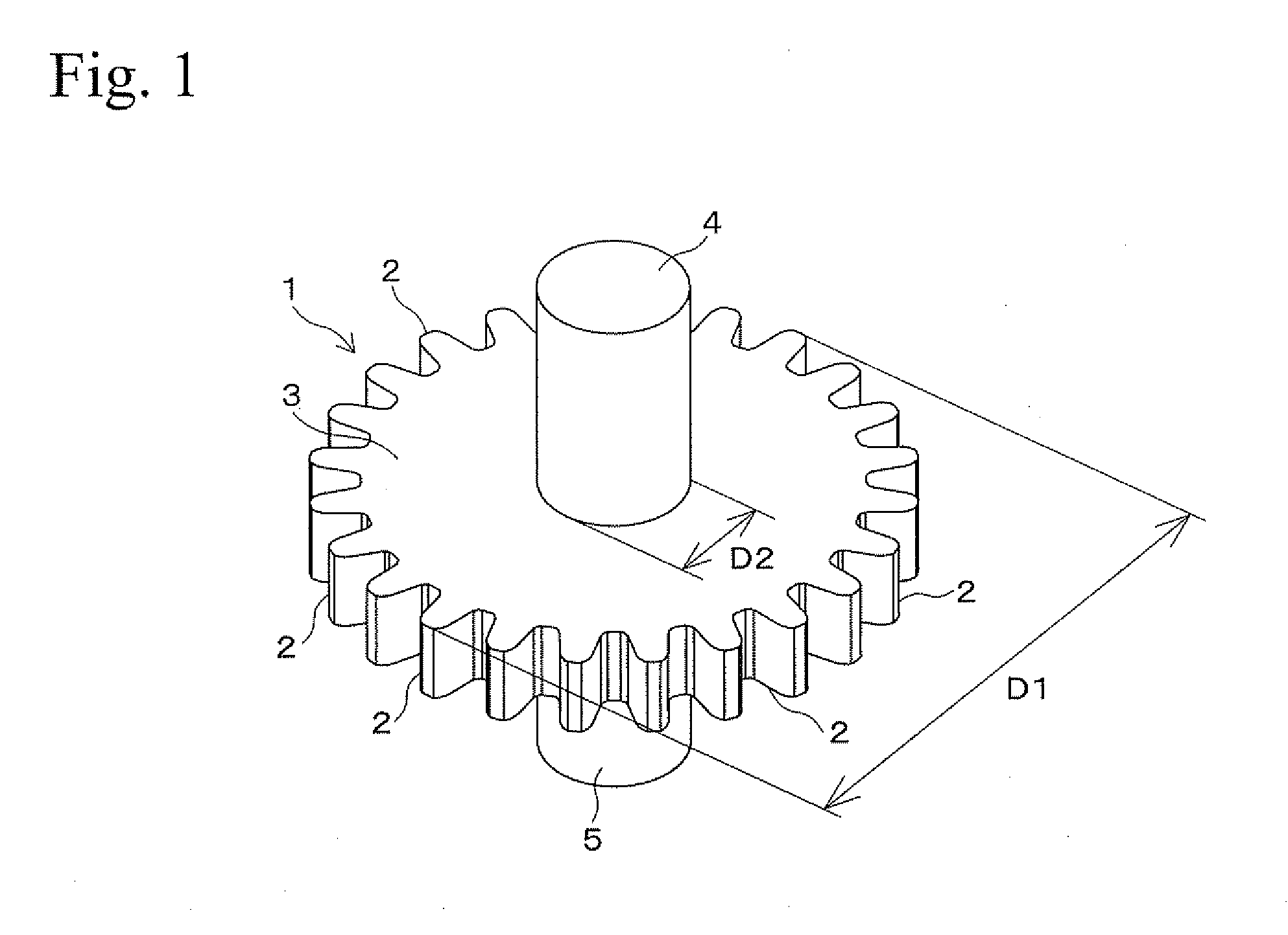
[0026]FIG. 1 shows a microgear (hereinafter called a “gear”) of a microcomponent. The gear 1 is obtained by sintering a green compact that is formed by a forming die assembly of a First Embodiment. The gear 1 has a spur wheel portion 3 and columnar shaft portions 4 and 5 which have the same length. The spur wheel portion 3 is formed with plural teeth 2 at the outer circumferential surface thereof. Each of the shaft portions 4 and 5 perpendicularly extends on either side from the center of the spur wheel portion 3. The gear 1 may have the following dimensions. For example, the spur wheel portion 3 has an outer diameter D1 of several hundred micrometers to several millimeters, and the shaft portions 4 and 5 have a diameter D2 of several dozen to several hundred micrometers.

1-2 Forming Die Assembly

(1-2-1) Structure

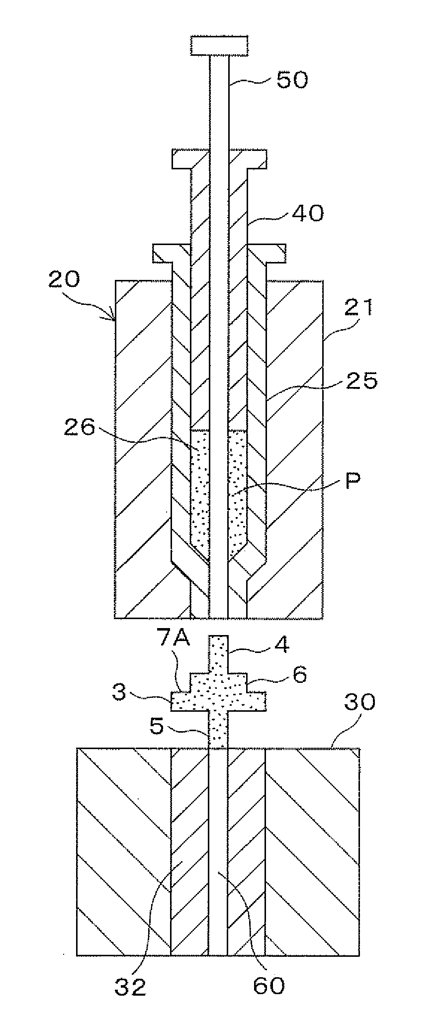
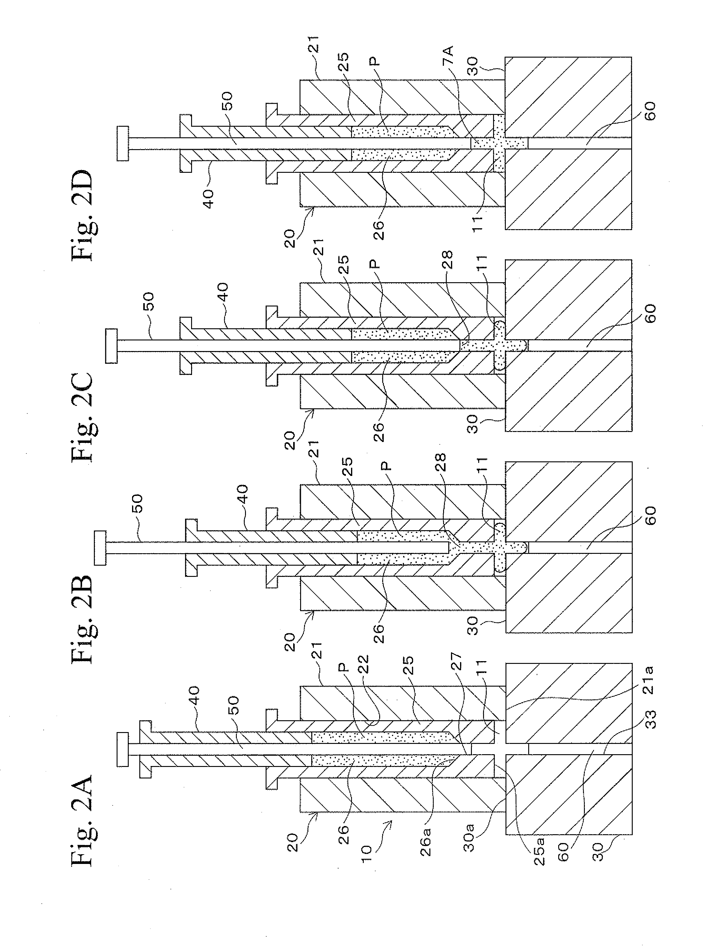
[0027]FIGS. 2A to 2D and FIGS. 3A to 3D show steps for forming a green compact of the gear 1 by a forming die assembly of a First Embodiment. F...

second embodiment

2 Second Embodiment

2-1 Microgear

[0041]FIG. 5 shows a microgear of a microcomponent. The gear 7 is obtained by sintering a green compact that is formed by a forming die assembly of a Second Embodiment. The gear 7 is a two-step gear in which a spur wheel portion 6 is formed on a side (upper side in FIG. 5) of a spur wheel portion 3. The spur wheel portion 6 has a smaller diameter, and the spur wheel portion 3 has a larger diameter. The spur wheel portion 6 is formed with plural teeth 2 at the outer circumferential surface thereof. The gear 7 also has shaft portions 4 and 5. The shaft portion 4 projects from the spur wheel portion 6, and the shaft portion 5 projects from the spur wheel portion 3. The gear 7 may have the following dimensions. For example, the spur wheel portion 3 has an outer diameter D1 of several hundred micrometers to several millimeters, and the shaft portions 4 and 5 have a diameter D2 of several dozen to several hundred micrometers.

2-2 Forming Die Assembly

(2-2-1) ...

third embodiment

3 Third Embodiment

3-1 Microgear

[0048]The forming die assembly of the Third Embodiment can be also used for forming the green compact of the gear 7 shown in FIG. 5.

3-2 Forming Die Assembly

[0049](3-2-1)

[0050]FIGS. 9A to 9D and FIGS. 10A to 10D show a forming step of a green compact of the gear 7 by the forming die assembly of the Third Embodiment. In the forming die assembly of the Third Embodiment, the cylindrical hole 22 of the outer die 21 of the upper die 20 has a lower end portion. This lower end portion is reduced in the diameter via a tapered portion 22b and is formed with a smaller diameter portion 22c. The inner die 25, which is formed so as to be slidably inserted into the cylindrical hole 22, has a lower end portion. This lower end portion is reduced in the outer diameter via a tapered portion 25b and is formed with a smaller diameter portion 25c so as to correspond to the shape of the lower end portion of the cylindrical hole 22. The smaller diameter portion 25c is formed ...


PUM

PropertyMeasurementUnit
diameter D2aaaaaaaaaa
volume %aaaaaaaaaa
plasticityaaaaaaaaaa

Abstract

A forming die assembly for microcomponents includes a forming die, a plunger, and a punch. The forming die is formed with an outer die, an inner die, a storage portion formed at the inner die, and a punch hole formed at the inner die. The inner die slidably inserted into the outer die forms a part of a cavity between the inner die and the outer die. The storage portion stores a raw material with a metal powder and a binder having plasticity. The punch hole connects the cavity and the storage portion and forms a gate therebetween. The plunger slidably inserted into the storage portion fills the raw material stored in the storage portion into the cavity through the punch hole. The punch is slidably inserted into the plunger, and it closes the gate and compresses the raw material in the cavity.

Description

BACKGROUND OF THE INVENTION[0001]1. Technical Field[0002]The present invention relates to a forming die assembly including dies that may be used for producing microcomponents such as microgears. In the dies, a raw material with a metal powder and a binder having plasticity is compacted into a green compact with a shape similar to that of the microcomponent.[0003]2. Background Art[0004]Recently, in the production of digital home appliances, advanced medical equipment, and IT devices, there are trends toward decreasing dimensions and increasing performances of the devices. Therefore, requirements for decreasing dimensions and wall thicknesses have been increasing for components of such devices. In view of this, although microcomponents basically have small dimensions and thin walls, the microcomponents are also required to be even smaller and have thinner walls. A production method for such microcomponents is disclosed in Japanese Patent Application of Laid-Open No. 2006-344581. In th...

Claims


Application Information

Patent Timeline
Patent Type & Authority Applications(United States)
IPC IPC(8): B29C45/72B29C45/02
CPCB22F3/03B22F2003/033B22F3/004B22F5/08B30B11/04B30B15/302B22F2003/023B30B11/02
Inventor MURASUGI, NARUTOSHIMAEKAWA, KAZUNORIISHIJIMA, ZENZO
Owner RESONAC CORP
Why Eureka
Try Eureka