Forming die assembly for microcomponents

Active Publication Date: 2012-05-03
RESONAC CORP
View PDF2 Cites 11 Cited by
  • Summary
  • Abstract
  • Description
  • Claims
  • Application Information

AI Technical Summary

Benefits of technology

[0011]Moreover, in the present invention, in order to improve the flowability of the raw material and to easily fill the raw material into the cavity, the forming die is preferably provided with a heating means for heating the raw mater

Problems solved by technology

In this case, since the raw material is different from a raw powder, which is used in an ordinary powder metallurgy process, and has plasticity, the raw material is difficult

Method used


Image

  • Forming die assembly for microcomponents
  • Forming die assembly for microcomponents
  • Forming die assembly for microcomponents

Examples


Embodiment Construction

[0018]Embodiments of the present invention will be described with reference to the figures hereinafter.
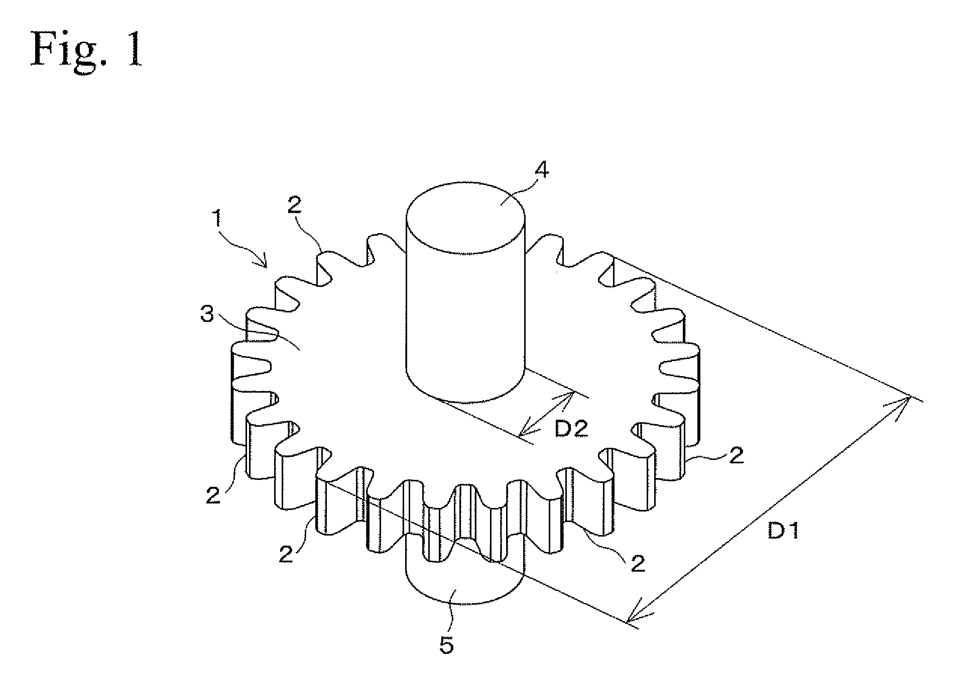
(1) Microgear

[0019]FIG. 1 shows a microgear (hereinafter called a “gear”) of a microcomponent. The gear 1 is obtained by sintering a green compact that is formed by a forming die assembly of an embodiment. The gear 1 has a spur wheel portion 3 and columnar shaft portions 4 and 5 which have the same length. The spur wheel portion 3 is formed with plural teeth 2 at the outer circumferential surface thereof. Each of the shaft portions 4 and 5 perpendicularly extends on either side from the center of the spur wheel portion 3. The gear 1 may have the following dimensions. For example, the spur wheel portion 3 has an outer diameter D1 of several hundred micrometers to several millimeters, and the shaft portions 4 and 5 have a diameter D2 of several dozen to several hundred micrometers.

(2) Forming Die Assembly

(2-1) Structure

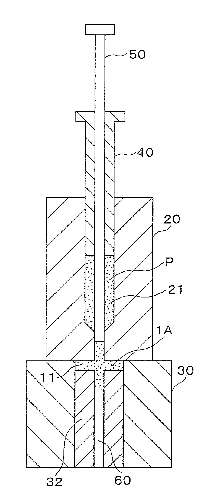
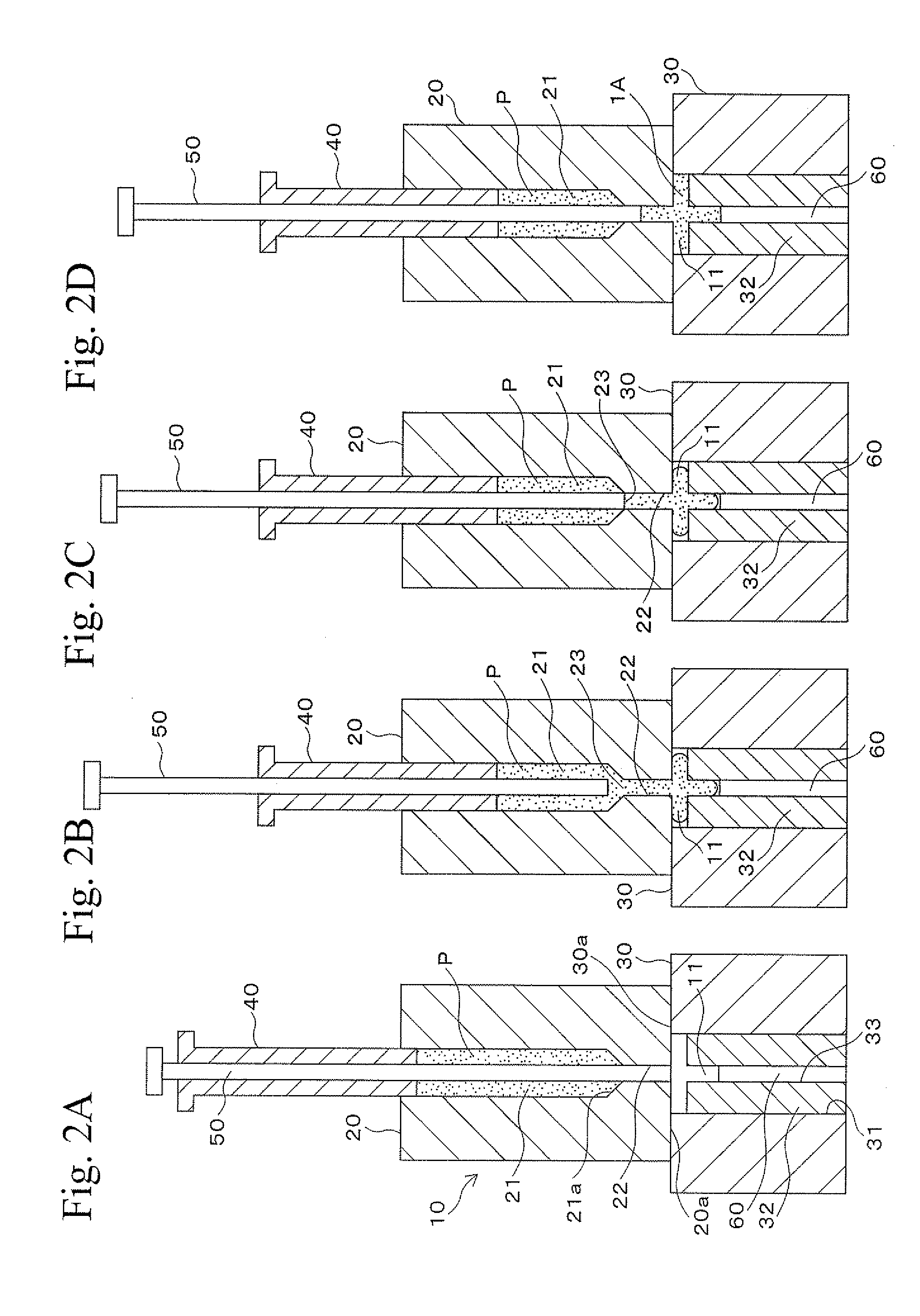
[0020]FIGS. 2A to 2D and FIGS. 3A to 3D show steps for forming a ...


PUM

PropertyMeasurementUnit
Plasticityaaaaaaaaaa

Abstract

A forming die assembly for microcomponents includes a forming die, a plunger, and a punch. The forming die is formed with a cavity, a storage portion for storing a raw material with a metal powder and a binder having plasticity, and a punch hole that connects the cavity and the storage portion so as to form a gate therebetween. The plunger is formed so as to be slidably inserted into the storage portion and to fill the raw material stored in the storage portion into the cavity through the punch hole. The punch is slidably inserted into the plunger in the sliding direction of the plunger and opens and closes the gate by reciprocatory sliding. The punch closes the gate and compresses the raw material in the cavity into a green compact by sliding in the direction of the cavity.

Description

BACKGROUND OF THE INVENTION[0001]1. Technical Field[0002]The present invention relates to a forming die assembly including dies that may be used for producing microcomponents such as microgears. In the dies, a raw material with a metal powder and a binder having plasticity is compacted into a green compact with a shape similar to that of the microcomponent.[0003]2. Background Art[0004]Recently, in the production of digital home appliances, advanced medical equipment, and IT devices, there are trends toward decreasing dimensions and increasing performances of the devices. Therefore, requirements for decreasing dimensions and wall thicknesses have been increasing for components of such devices. In view of this, although microcomponents basically have small dimensions and thin walls, the microcomponents are also required to be even smaller and have thinner walls. A production method for such microcomponents is disclosed in Japanese Patent Application of Laid-Open No. 2006-344581. In th...

Claims


Application Information

Patent Timeline
IPC IPC(8): B29C45/72B29C45/02
CPCB22F3/004B22F3/03B22F5/08B30B11/04B30B15/302B22F2003/023B22F2003/033B30B11/02
Inventor MURASUGI, NARUTOSHIMAEKAWA, KAZUNORIISHIJIMA, ZENZO
Owner RESONAC CORP
Why Eureka
Try Eureka