Multi-Lobed and Constant Contact Gear Mechanism

a constant contact, multi-lobe technology, applied in the direction of rod connections, shafts and bearings, fastening means, etc., can solve the problems of high stress on the output shaft of the transmission, and the damage of the transmission shaft by the square splines

Inactive Publication Date: 2012-05-03
FOLEY GUY +1
View PDF8 Cites 16 Cited by
  • Summary
  • Abstract
  • Description
  • Claims
  • Application Information

AI Technical Summary

Benefits of technology

[0014]In view of the foregoing disadvantages inherent in the known types of gear spline designs now present in the prior art, the present invention provides a new lobed gear interface wherein the same can be utilized for providing convenience for the user when providing an improved, efficient and robust means of transferring torque between vehicle drivetrain components.
[0016]Another object of the present invention to provide a lobed gear interface that provides uniform contact across its entire outer surface to improve durability, reduce mechanical stress on components and improve torque transmission capability.

Problems solved by technology

The use of square splines has been standard industry practice for many years and an effective method of transmitting torque from the transmission output shaft to the slip yoke; however their use leads to some drawbacks with regard to the reliable operation of the vehicle and the drivetrain assembly.
Square splines create a high magnitude of stress at the contact points along the splines during operation, which is brought on by clashing and single-point contacts at the spline contact interface.
Square splines commonly create shutters throughout the drivelines, develop material galling, allow the cross yokes to deteriorate rapidly and allow for output shaft damage of the transmission in some cases.

Method used


Image

  • Multi-Lobed and Constant Contact Gear Mechanism
  • Multi-Lobed and Constant Contact Gear Mechanism
  • Multi-Lobed and Constant Contact Gear Mechanism

Examples


Embodiment Construction

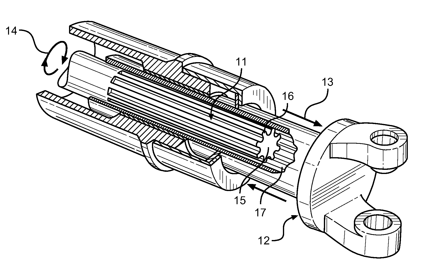
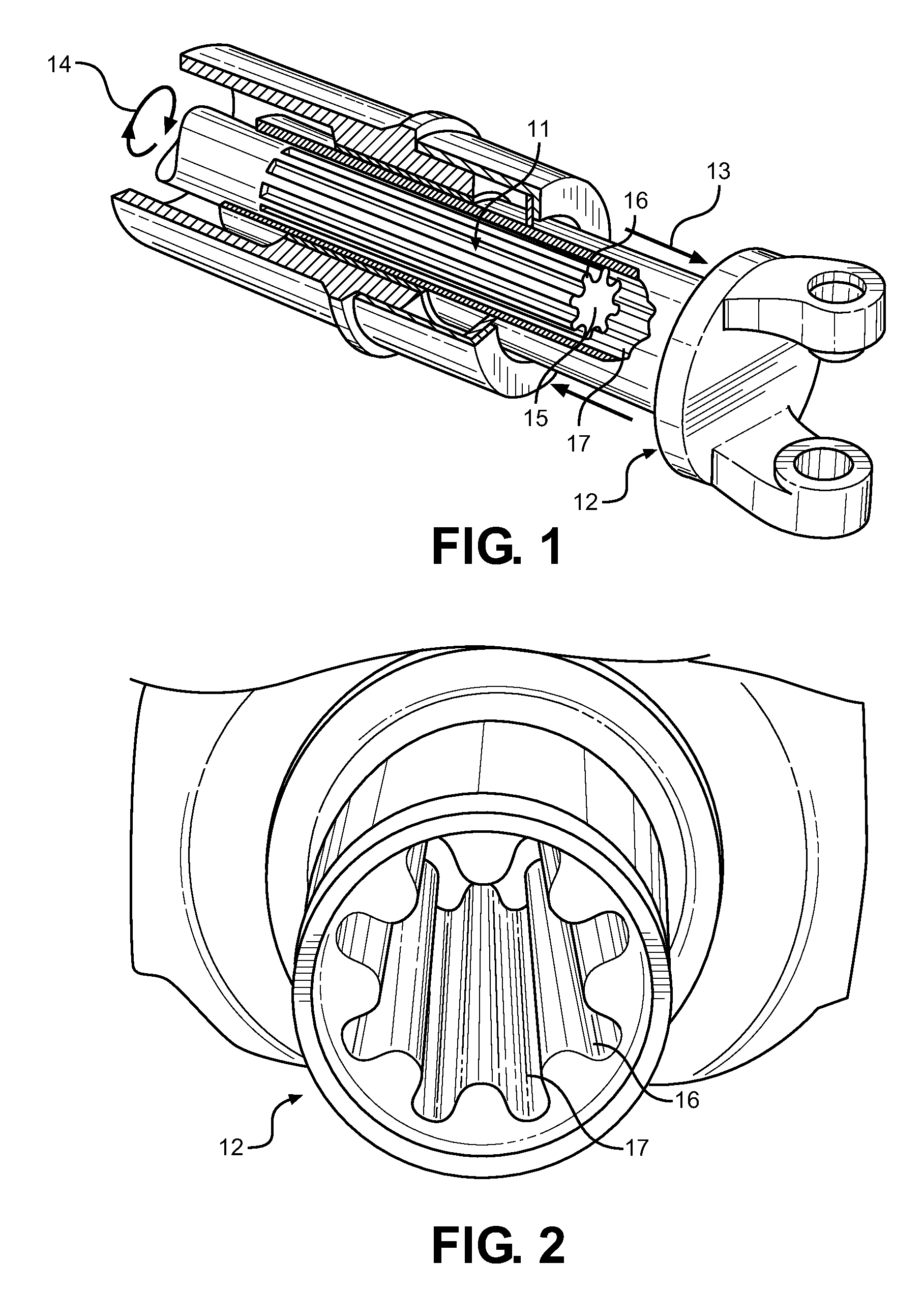
[0026]Referring now to FIG. 1, there is shown a view of the present invention being utilized in a vehicular slip yoke configuration, wherein torque 14 is being supplied from a vehicle transmission output shaft 11 to a slip yoke 12 at the rear axle of a vehicle. The transmission output shaft 11 is a shaft from the vehicle transmission that is utilized to power the rear wheels of a truck or similar vehicle. In this application, the shaft 11 is slideably mounted within a corresponding slip yoke 12 shaft. The connection between the two allows the transmission shaft 11 and slip yoke 12 to displace 13 with regard to one another and still remain in contact. The present invention is being employed at the slip yoke 12 and shaft 11 interface, wherein splines of the shaft 11 are generally utilized to transmit torque from one structure to the other. The splines of the present invention are alternatively a plurality of lobes 16, which are formed from a sinusoidal outer surface profile 17 that fo...


PUM


Abstract

A multi-lobed gear system is provided in which the lobes of an input gear and a corresponding, mating pair of lobes in an output gear are uniformly in contact. The lobed gear tooth profile of the present invention reduces material galling, shuttering and whipping within a drivetrain assembly in comparison to square or helical splines that incorporate single point contacts between meshed pairs. An internal pinion gear or slip yoke internal shaft employs a lobed gear tooth profile that forms a sinusoidal outer perimeter shape. The perimeter surface is in constant contact with the complementary shaft or gear across its entire surface. A small clearance gap may be provided for lubrication, fitment and manufacturing considerations.

Description

CROSS REFERENCE TO RELATED APPLICATION[0001]This application claims the benefit of U.S. Provisional Application No. 61 / 407,228 filed on Oct. 27, 2010, entitled “Multi-Lobed Slip Yoke.”BACKGROUND OF THE INVENTION[0002]1. Field of the Invention[0003]The present invention relates to transmission systems and gear tooth profiles. More specifically, the present invention relates to a sinusoidal gear spline shape that forms a lobed gear, offering superior contact between meshed gears, particularly suited for automotive drivetrain applications.[0004]2. Description of the Prior Art[0005]Slip yokes are critical drivetrain components for trucks and off-road vehicles, and provide a means that compensates for extreme rear suspension travel in these types of vehicles. The slip yoke is an outer shaft with an inner set of splines that mate with a transmission output shaft. The output shaft is inserted into the interior of the slip yoke, which accepts its rotational output while permitting fore-aft ...

Claims


Application Information

Patent Timeline
Patent Type & Authority Applications(United States)
IPC IPC(8): F16D3/06F16B7/00
CPCF16D3/06Y10T403/7035
Inventor FOLEY, GUYDANSON, WILIIAM
Owner FOLEY GUY
Why Eureka
Try Eureka