Solar desalination system with reciprocating solar engine pumps

Inactive Publication Date: 2012-05-10
KENERGY SCI
View PDF7 Cites 24 Cited by
  • Summary
  • Abstract
  • Description
  • Claims
  • Application Information

AI Technical Summary

Benefits of technology

[0033]The present invention is a solar desalination system for creation of desalinated water from seawater that also produces electricity. The present invention system includes: a) a solar furnace unit, including a vessel for receiving and evaporating seawater to create desalinated steam, and a solar energy concentrator positioned adjacent the vessel to concentrate solar energy to the vessel; b) input means for feeding seawater to the vessel; c) brine output means for removal of brine water bottoms from the vessel; d) a riser pipe having a top and a bottom and being connected at its bottom to and extending upwardly from the vessel for transporting steam from the vessel, the riser pipe top positioned at a predetermined vertical height from the vessel; e) an electric power-producing steam turbine generator positioned at a predetermined vertical height from the vessel, and connected to the top of the riser pipe for production of electric power with steam from the vessel; f) a drop pipe having a top and a bottom, and being connected at its top to the steam turbine generator for removal of desalinated water from the steam turbine generator; g) an electric power-producing hydroturbine generator connected to the bottom of the drop pipe for production of electric power with desalinated water from the steam turbine generator; and, h) egress means for removal of desalinated water from the hydroturbine generator for subsequent use; wherein the input means for feeding seawater into the vessel includes: 1) at least one pump adapted to feed seawater into the vessel, having a drive means selected from the group consisting of mechanical drive means, direct drive electrical means, and electrical storage means; 2) a seesawing platform having a central fulcrum support upon which the platform is moveably positioned to reciprocally rotate through a predetermined arc, the predetermined arc having a bottom, the bottom being the arc base; 3) a first solar heat-receiving closed container located on the platform on a first side of the central fulcrum support and a second solar heat-receiving closed container located on the platform on a second side of the central fulcrum support and opposite the first side; 4) at least one solar reflector

Problems solved by technology

U.S. Pat. No. 4,132,223 to E. Garland Reddell describes a pivotally mounted solar energy collector is maintained oriented towards the sun by creating a continuing imbalance of the collector about its pivotal axis resulting in p

Method used


Image

  • Solar desalination system with reciprocating solar engine pumps
  • Solar desalination system with reciprocating solar engine pumps
  • Solar desalination system with reciprocating solar engine pumps

Examples


Embodiment Construction

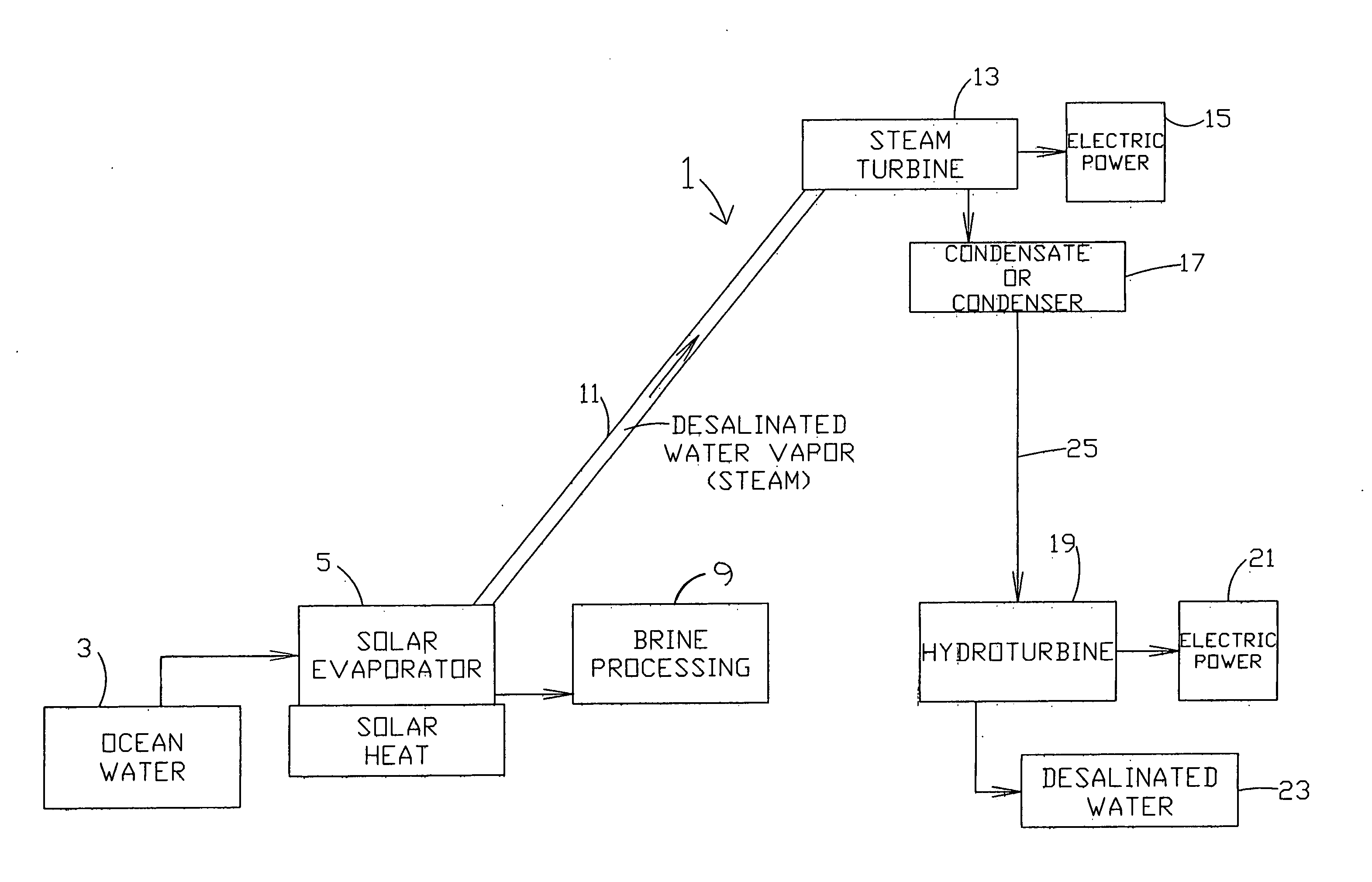
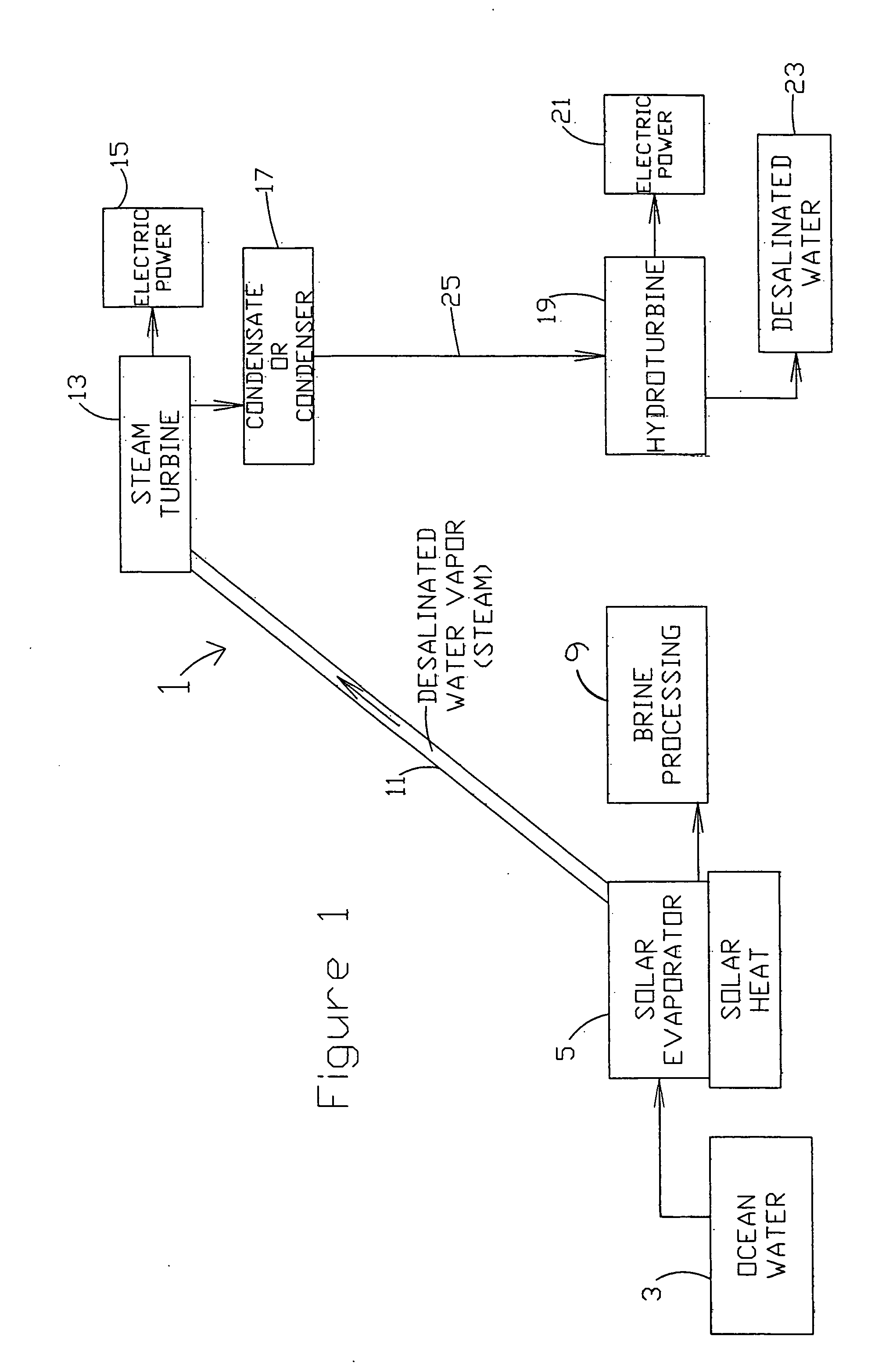
[0087]FIG. 1 is a block diagram of some preferred embodiments of a present invention solar desalination system 1. Present invention system 1 includes a supply of salt water, here ocean water 3, that is fed to or pumped (not shown) to solar evaporator 5. Solar evaporator 5 may be any solar evaporator that has been heretofore suggested or taught and thus may be a flat mirror array for reflecting vast areas of sunlight so as to be directed to a container or vessel for evaporating water out of the saline water. Alternatively, it could be a parabolic dish solar concentrator device or any other solar evaporator or furnace. The size of the solar evaporator 5 is dependent upon the ambient temperature and the volume of ocean water (capacity of the vessel) being used. Thus, solar heat 7 provides the evaporator 5 with heat energy to generate desalinated water vapor (steam that moves up riser pipe 11 a predetermined height, e.g., 200 feet), to steam turbine 13. Steam turbine 13 will be installe...


PUM

PropertyMeasurementUnit
Lengthaaaaaaaaaa
Transparencyaaaaaaaaaa
Energyaaaaaaaaaa

Abstract

A solar desalination system includes a solar furnace for receiving seawater into a vessel and concentrating sunlight on the vessel to heat that water using solar energy to create desalinated steam. Water is input into the furnace via a pump that is powered by a reciprocating solar engine. The reciprocating solar engine includes a seesawing platform with a closed system of two or more connected containers thereon. Solar heating causes a fluid to move from one container to another causing the platform to reciprocally rotate through a predetermined arc, creating energy that can be harnessed. A riser pipe extending upwardly from the solar furnace carries steam to an electric power-producing steam turbine generator where the steam generates electricity. A drop pipe extending downwardly from the steam turbine generator carries desalinated water to an electric power-producing hydroturbine generator where the water generates electricity and is then removed for subsequent use.

Description

CROSS-REFERENCE TO RELATED APPLICATIONS[0001]This application is a continuation-in-part of the following copending United States Applications by the same inventors herein: Ser. No. 12 / 387,430, filed on May 1, 2009, titled “Solar Desalination System”; Ser. No. 12 / 319,248, filed on Jan. 5, 2009, titled “Reciprocating Solar Engine”; Ser. No. 12 / 321,402, filed on Jan. 20, 2009, titled “Reciprocating Solar Engine with Attached Solar Windows”; and Ser. No. 12 / 383,353, filed on Mar. 23, 2009, titled “Reciprocating Solar Engine with Solar Reflectors.”BACKGROUND OF INVENTION[0002]a. Field of Invention[0003]The invention relates generally to systems that provide for the conversion of salt water to desalinated water and for the generation of electric power. More specifically, the present invention relates to systems that utilize reciprocating solar engine pumps to pump saline water to a solar evaporator where solar energy is used to separate water from salt in saline water and the resulting ev...

Claims


Application Information

Patent Timeline
IPC IPC(8): H02K7/18
CPCB01D1/0035Y02E60/17B01D5/006B01D5/0081C02F1/001C02F1/14C02F1/32C02F2103/08C02F2303/04F01K17/04F03B13/06F03G6/065Y02E10/22Y02E10/46B01D3/007Y02W10/37Y02A20/142Y02A20/212Y02A20/124Y02E10/20Y02E60/16Y02P70/10
Inventor GLYNN, KENNETH P.
Owner KENERGY SCI
Why Eureka
Try Eureka