Eureka AIR delivers breakthrough ideas for toughest innovation challenges, trusted by R&D personnel around the world.

Thermal control power device

Inactive Publication Date: 2012-05-10
WELL SHIN TECH +1
View PDF19 Cites 2 Cited by
  • Summary
  • Abstract
  • Description
  • Claims
  • Application Information

AI Technical Summary

Benefits of technology

[0006]As described above, the thermal control power device of the present invention drives the driving circuit to control the switch states of the electromagnetic relay and further automatically switch on / off the external electric appliance, by means of utilizing the temperature setting switch to make choice of one constant temperature, utilizing the thermal detector to detect the environment temperature, and then utilizing the microcontroller to compare the detected environment temperature and the selected constant temperature so as to output corresponding control signals to the driving circuit. Therefore, even if users forget to shut off the electric appliances by hand, the thermal control power device of the present invention still can avoid waste of power or damage of the electric appliances due to long-term use.

Problems solved by technology

However, the electric appliances, such as electric fans and warmers, often need to work under specific environment temperature.
If the power devices are always connected with the power supply with power switches of the electric appliances not yet turned off, then a circuit will always be formed to continually consume a current so that results in waste of power.
In addition, the electric appliances may be subjected to sustained high environment temperature due to long-term use.
As a result, the electric appliances are apt to be damaged by the high environment temperature.
It is inconvenient to use.

Method used


Image

  • Thermal control power device
  • Thermal control power device
  • Thermal control power device

Examples


Embodiment Construction

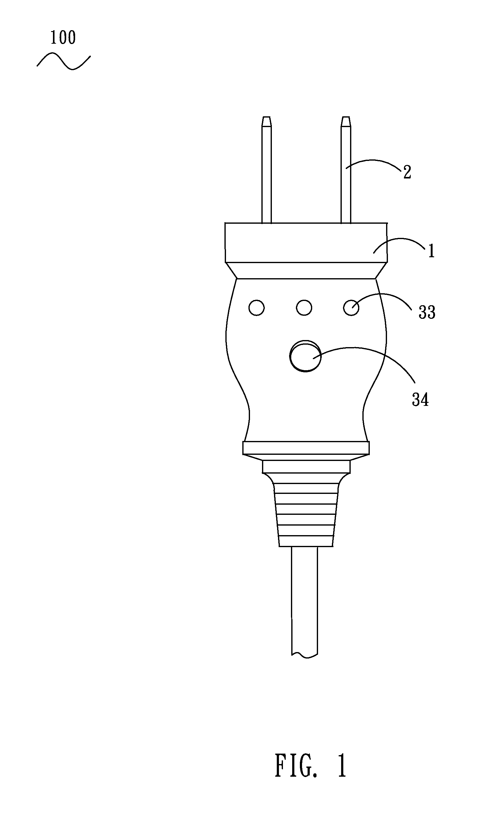
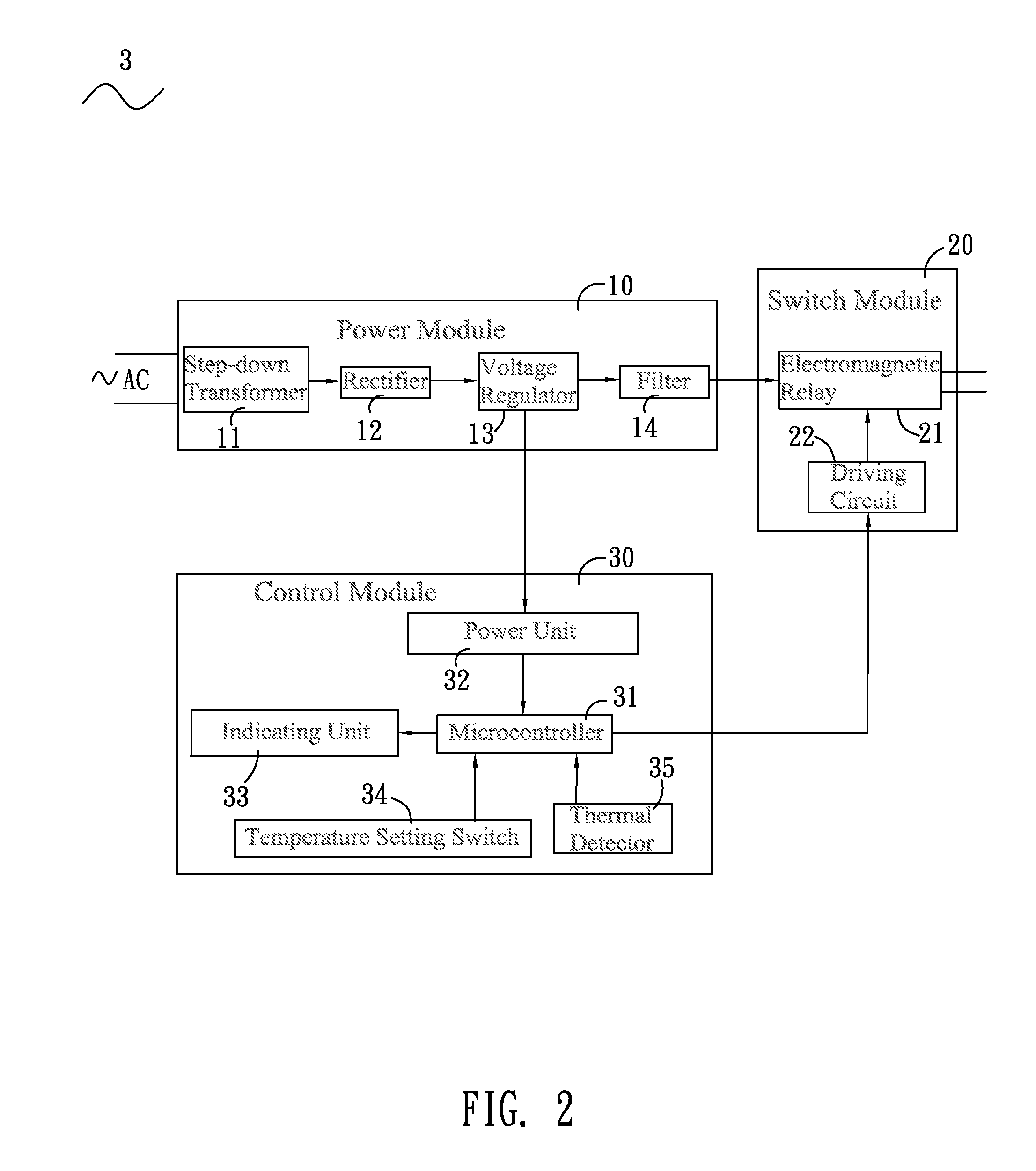
[0012]With reference to FIG. 1 and FIG. 2, a thermal control power device 100 according to an embodiment of the prevent invention includes an insulating housing 1, a plurality of conductive terminals 2 and a thermal control circuit 3. In this embodiment, the insulating housing 1 is an ordinary plug housing. The conductive terminals 2 are embedded in the insulating housing 1 and partially stretch out of the insulating housing 1 for connecting with an AC power supply. The thermal control circuit 3 is disposed in the insulating housing 1 and includes a power module 10, a switch module 20 and a control module 30.

[0013]Referring to FIG. 2 and FIG. 3, the power module 10 is connected with the conductive terminals 2 for getting an AC input voltage. The power module 10 includes a step-down transformer 11, a rectifier 12, a voltage regulator 13 and a filter 14 which are successively connected together. The voltage regulator 13 has a comparator U1 and a first transistor Q1 of which the collec...


PUM


Abstract

A thermal control power device has a thermal control circuit which includes a power module for getting and dealing with an AC input voltage, a control module, and a switch module having an electromagnetic relay and a driving circuit. The control module includes a microcontroller having a plurality of specific temperature value of constant temperatures therein, a power unit regulating an output voltage of the power module and providing a work voltage for the microcontroller, a temperature setting switch making choice of one of the constant temperatures, and a thermal detector detecting an environment temperature under which an external electric appliance works. The microcontroller compares the environment temperature with the constant temperature and then sends out corresponding control signals. The driving circuit controls switch states of the electromagnetic relay according to the control signals so as to further automatically control the electric appliance on-off.

Description

BACKGROUND OF THE INVENTION[0001]1. Field of the Invention[0002]The present invention generally relates to a power device, and more particularly to a thermal control power device.[0003]2. The Related Art[0004]Power devices, such as plugs, are generally employed to be connected with a power supply so as to make the power supply provide power for electric appliances. However, the electric appliances, such as electric fans and warmers, often need to work under specific environment temperature. If the power devices are always connected with the power supply with power switches of the electric appliances not yet turned off, then a circuit will always be formed to continually consume a current so that results in waste of power. In addition, the electric appliances may be subjected to sustained high environment temperature due to long-term use. As a result, the electric appliances are apt to be damaged by the high environment temperature. So the users often need to pull out all the power d...

Claims


Application Information

Patent Timeline
IPC IPC(8): H01H47/26
CPCH01H37/12H02H5/042H02H3/04H01H47/26
Inventor WU, JUI-HSIUNG
Owner WELL SHIN TECH
Why Eureka
Eureka Blog
Learn More