Duty factor probing of a triac-based dimmer

a triac-based dimmer and duty factor technology, applied in the direction of frequency measurement arrangement, instruments, semiconductor lamp usage, etc., can solve the problem of difficult operation of typical thyristor-based dimmers, and achieve the effect of improving efficiency

Inactive Publication Date: 2012-05-10
SIGNIFY HLDG BV
View PDF3 Cites 57 Cited by
  • Summary
  • Abstract
  • Description
  • Claims
  • Application Information

AI Technical Summary

Benefits of technology

[0009]The power supply circuit includes a circuit that probes the output of the dimmer from the turn-on time of the dimmer until enough information has been gathered to correctly predict a next zero-crossing of the AC line voltage that supplies the dimmer. The dimming value is determined from the time between the predicted ze

Problems solved by technology

In particular, in dimmable high-efficiency replacement light bulbs, the low energy requirements of the lighting devices makes it difficult for the typical thyristor-based dimmers to operate properly, a

Method used


Image

  • Duty factor probing of a triac-based dimmer
  • Duty factor probing of a triac-based dimmer
  • Duty factor probing of a triac-based dimmer

Examples


Embodiment Construction

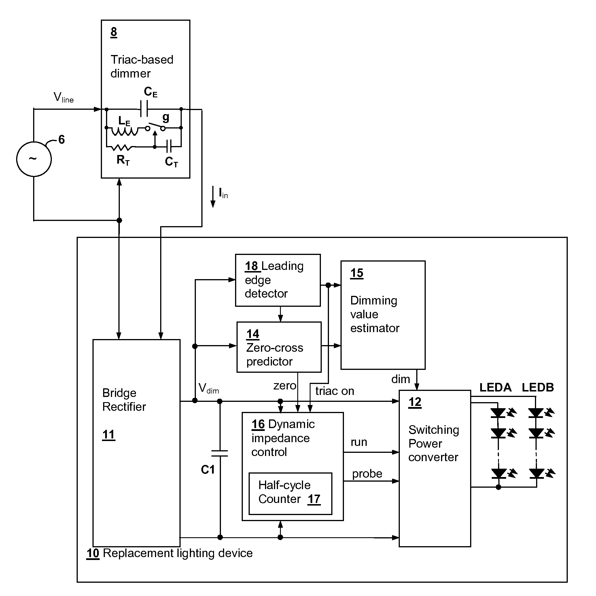
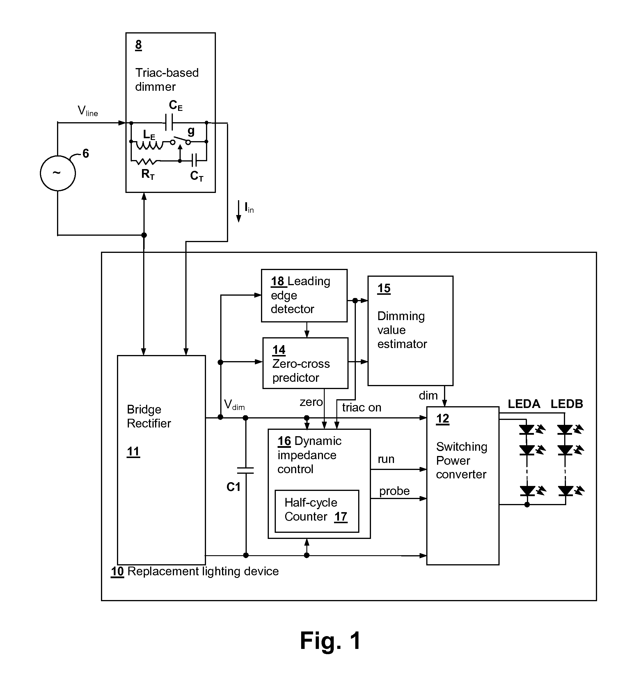
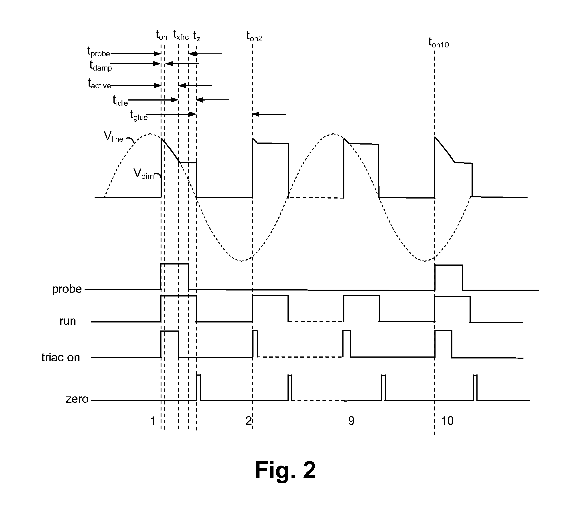
[0016]The present invention encompasses circuits and methods for powering and controlling lighting devices. In particular embodiments, strings of light-emitting diodes (LEDs) are packaged to replace incandescent lamps, and the energy supplied to the LED strings is varied in accordance with a dimming value determined from operation of a thyristor-controlled dimmer supplying the replacement lighting device, so that dimmed operation is achieved. The present invention achieves dimming operation efficiently, while still correctly determining the dimming setting of the dimmer, i.e., the dimming value by probing the output of the dimmer periodically or intermittently. The dimming value is needed to determine the amount of current to supply to the LED strings and must be determined initially and tracked as changes occur in the dimmer setting. Further, periodically it is desirable to ensure that the dimming value has been estimated correctly, so that errors and drift are reduced or eliminate...


PUM


Abstract

A power supply circuit for operating high-efficiency lighting devices from a thyristor-controlled dimmer determines the dimming value, i.e., the dimmer duty factor by periodically probing the dimmer output. A minimum conductance is applied across the output of the dimmer during probing intervals that begin at the turn-on time of the dimmer and last until enough information has been gathered to correctly predict a next zero crossing of the AC line voltage that supplies the input of the dimmer. The dimming value is determined from the time interval between the predicted zero-crossing and a next turn-on time of the dimmer. The probing can be performed at intervals of an odd number of half-cycles of the AC line frequency so that a DC offset is not introduced within internal timing circuits of the dimmer. The AC line frequency can also be determined from a time interval between the predicted zero crossings.

Description

[0001]The present U.S. patent application claims priority under 35 U.S.C. §119(e) to U.S. Provisional Patent Application Ser. No. 61 / 410,269 filed on Nov. 4, 2010. The present U.S. patent application also claims priority under 35 U.S.C. §120 to U.S. patent application Ser. No. 13 / 194,531 entitled “POWERING HIGH-EFFICIENCY LIGHTING DEVICES FROM A TRIAC-BASED DIMMER”, filed on Jul. 29, 2011 and to U.S. patent application Ser. No. 12 / 858,164 entitled “DIMMER OUTPUT EMULATION”, filed on Aug. 17, 2010, each having at least one common inventor with the present U.S. patent application and which are assigned to the same Assignee. Therefore, the present U.S. patent application is a Continuation-in-Part of the above-referenced non-provisional U.S. patent applications, the disclosures of which are incorporated herein by reference.BACKGROUND OF THE INVENTION[0002]1. Field of the Invention[0003]The present invention relates generally to lighting device power sources such as those included within...

Claims


Application Information

Patent Timeline
IPC IPC(8): H05B37/02G01R31/327H05B44/00
CPCH05B33/0815G01R23/02Y02B20/346H05B33/0845H05B45/10Y02B20/30H05B45/375H05B45/385
Inventor KING, ERICMELANSON, JOHN L.
Owner SIGNIFY HLDG BV
Why Eureka
Try Eureka