Low-Dropout Regulator

a voltage regulator and low-dropout technology, applied in the direction of electric variable regulation, process and machine control, instruments, etc., can solve the problems of high current consumption in the current-limiting loop, consumption increasing even greater, and the current-limiting loop already consumes close to half of the objective, so as to reduce current consumption and good accuracy

Active Publication Date: 2012-05-10
TELEFON AB LM ERICSSON (PUBL)
View PDF7 Cites 25 Cited by
  • Summary
  • Abstract
  • Description
  • Claims
  • Application Information

AI Technical Summary

Benefits of technology

[0035]Therefore a need exists for an LDO regulator comprising a current-limiting loop that offers good accuracy and has reduced current consumption.
[0044]With a regulator of the invention, it is possible to save significant amounts of current, which facilitates the design of LDO regulators. The current consumption of the current-limiting loop constituted a very large part of the current consumed by regulators of the prior art.
[0045]In addition, the regulator of the invention allows more precise limiting of the current.
[0061]In these embodiments it is possible to create replication (or copy) transistors that have a significant gate surface area. This facilitates pairing with the power transistor.
[0062]In addition, in these embodiments, there is great flexibility in the choice of parameters that set the limit for the output current.

Problems solved by technology

The current consumption is very high in this current-limiting loop.
In addition, this consumption grows even greater as the size of the power transistor T11 decreases.
The current-limiting loop therefore already consumes close to half of the objective.
However, the topography of the circuit does not allow much reduction in this parameter.
However, there is almost no room for adjustment here because the output current depends on W11.
In addition, the accuracy of the current-limiting loop is very low because the pairing of the transistors T10 and T11 is made difficult by their difference in surface area which can have a ratio as high as 2000 or more.
One can see that it is difficult to pair these two transistors because almost the entire surface area of the silicon is occupied by T11.
This level of accuracy is low, and does not take into account the effects of temperature and voltage offsets.
When such phenomena are taken into account, the result is an even lower accuracy.

Method used


Image

  • Low-Dropout Regulator
  • Low-Dropout Regulator
  • Low-Dropout Regulator

Examples


Embodiment Construction

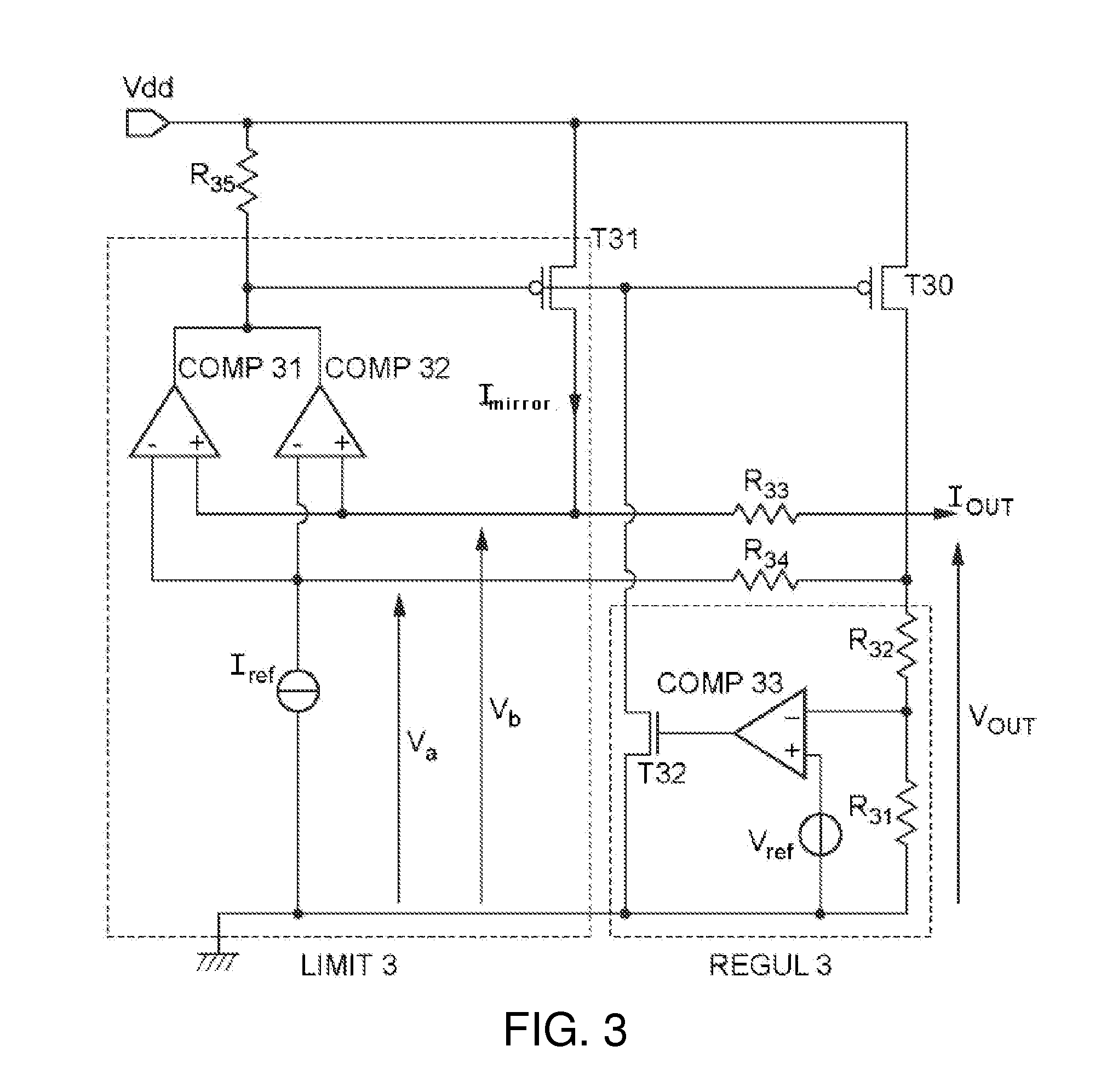
[0072]A circuit according to an embodiment of the invention is described below, first with reference to FIG. 3.

[0073]The circuit is represented in this figure, in which a regulating loop REGUL3 and a current-limiting loop LIMIT3 can be recognized.

[0074]The regulating loop comprises two resistors in series R31 and R32 connecting the output voltage Vout to the ground. The node between the resistors R31 and R32 is coupled to the non-inverting input of a comparator COMP33. The inverting input of this comparator is coupled with a reference voltage source Vref.

[0075]Thus the output voltage from the comparator COMP33 is a linear combination of the output voltage Vout and the reference voltage Vref. This is equivalent to comparing the output voltage to a reference voltage Vref′ whose value is a function of the reference voltage Vref and the value of the resistors R31 and R32. The output voltage of the comparator COMP33 can be written as:

Vs33=G33·R31R31+R32·(VOUT-R31+R32R31·Vref),

where G33 i...


PUM


Abstract

The invention proposes a low-dropout voltage regulator comprising an output terminal for providing an output voltage (Vout) regulated as a function of a reference voltage, and for providing an output current (Iout), and additionally comprising an output current limiting unit (LIMIT3), with said unit comprising:—replication means for replicating the output current (T31) to provide a mirror current of the output current (Imirror),—comparison means (COMP31, COMP32) for comparing the mirror current with a reference current (Iref),—feedback means for supplying feedback (COMP31, COMP32, R35, REGUL3) to the regulator in order to limit the output current when the mirror current is greater than the reference current, and the mirror current is injected into the output terminal.

Description

TECHNICAL FIELD[0001]The present invention relates to Low-Dropout (LDO) voltage regulator circuits.[0002]More particularly it concerns the limiting of short circuit current in such regulators.TECHNOLOGICAL BACKGROUND[0003]An LDO regulator allows providing a stable output voltage in spite of fluctuations in the general supply voltage of the circuit in which it is installed.[0004]When a circuit containing an LDO regulator is powered up, or when there is an accidental short circuit of the regulator output, it is necessary to limit the output current to avoid malfunctions.[0005]In order to limit this short circuit current, one can consider the use of dedicated current-limiting circuits. These circuits would consist of a feedback loop which measures the output current of the regulator, then compares it to a reference current in order to act on the regulator when the output current becomes greater than the reference current.[0006]Such a current-limiting circuit is shown in FIG. 1.[0007]In...

Claims


Application Information

Patent Timeline
Patent Type & Authority Applications(United States)
IPC IPC(8): G05F1/10
CPCG05F1/575G05F1/573
Inventor PONS, ALEXANDRE
Owner TELEFON AB LM ERICSSON (PUBL)
Why Eureka
Try Eureka