Nail print apparatus and print controlling method

a technology of nail print and control method, which is applied in the direction of printers, packaging foodstuffs, instruments, etc., can solve the problems of ink mist spreading around the nail, finger becoming dirty, and heavy burden on users, so as to achieve easy nail printing, simple method without troubling users, and easy nail printing

Active Publication Date: 2012-05-10
CASIO COMPUTER CO LTD
View PDF3 Cites 48 Cited by
  • Summary
  • Abstract
  • Description
  • Claims
  • Application Information

AI Technical Summary

Benefits of technology

[0030]According to the present invention, the user can easily make a nail chip with an outline form which fits the outline form of a nail section of the user without troubling the user. With this, the burden of the user such as the finger becoming dirty by the ink or the print substance when nail print is performed, or waiting without moving the finger while print operation is performed can be omitted. Moreover, nail print can be enjoyed by simply attaching a nail chip on which the design is printed on the user's nail section. Conseque

Problems solved by technology

However, there is a problem that, as in conventional nail print apparatuses where printing is performed by spraying ink directly on an upper surface of a nail of a person, the user needs to wait with the finger fixed without movement during the print operation, and this is a heavy burden on the user.
Moreover, when printing is performed using a print head of an ink jet method, there is a possibility that ink mist spreads around the nail, and there is a possibility that the ink attaches to the finger and the finger becomes dirty when printing is performed.
Further, when printing is performed directly on the nail, when the user desires to change the printed design image to a different design image, the user needs to erase the printed image using a nail polish remover, etc. and this is troublesome.
Therefore, there is a problem that the us

Method used


Image

  • Nail print apparatus and print controlling method
  • Nail print apparatus and print controlling method
  • Nail print apparatus and print controlling method

Examples


first embodiment

[0101]First, the first embodiment of a nail print apparatus of the present invention is described with reference to FIG. 1 to FIG. 29.

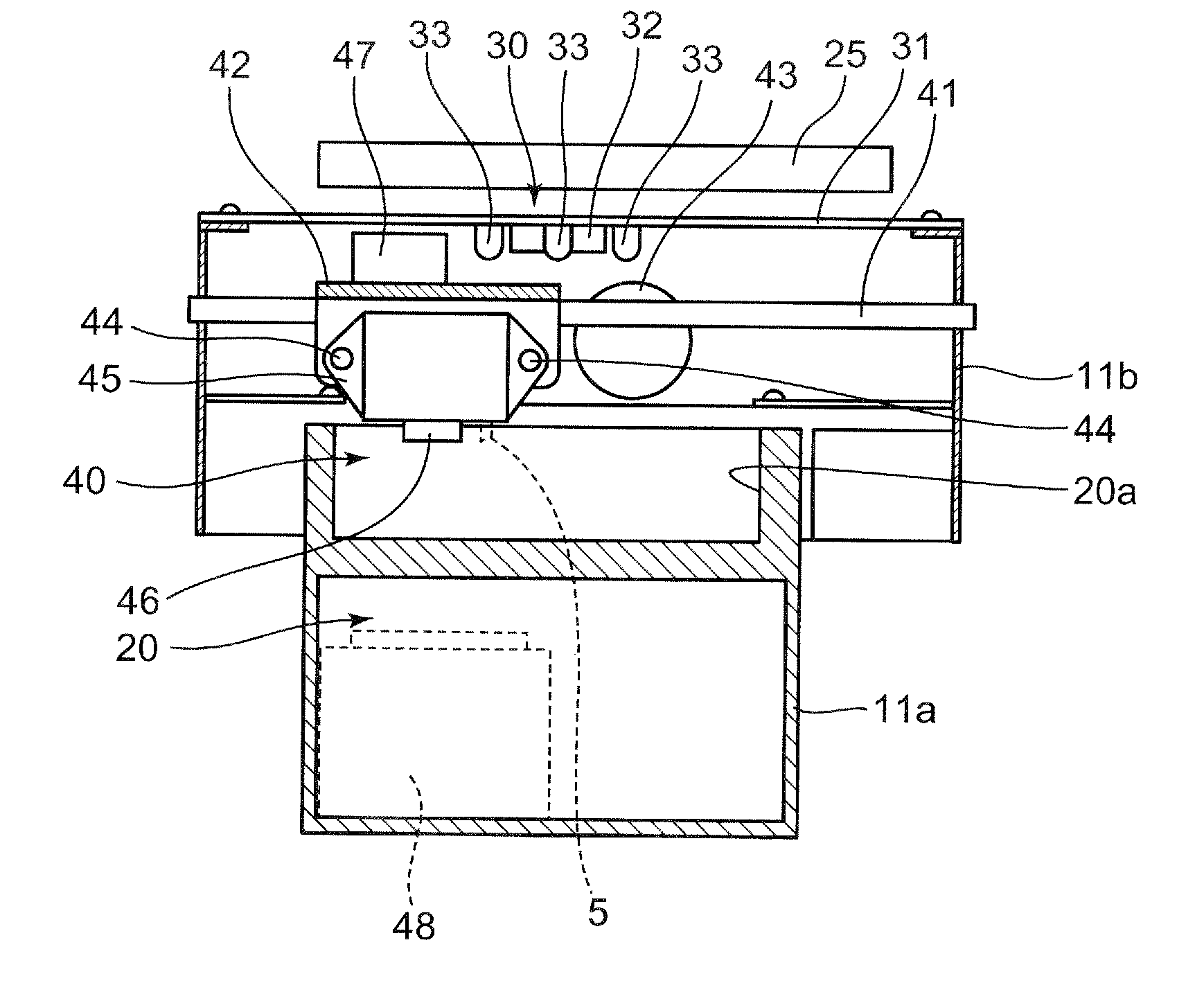
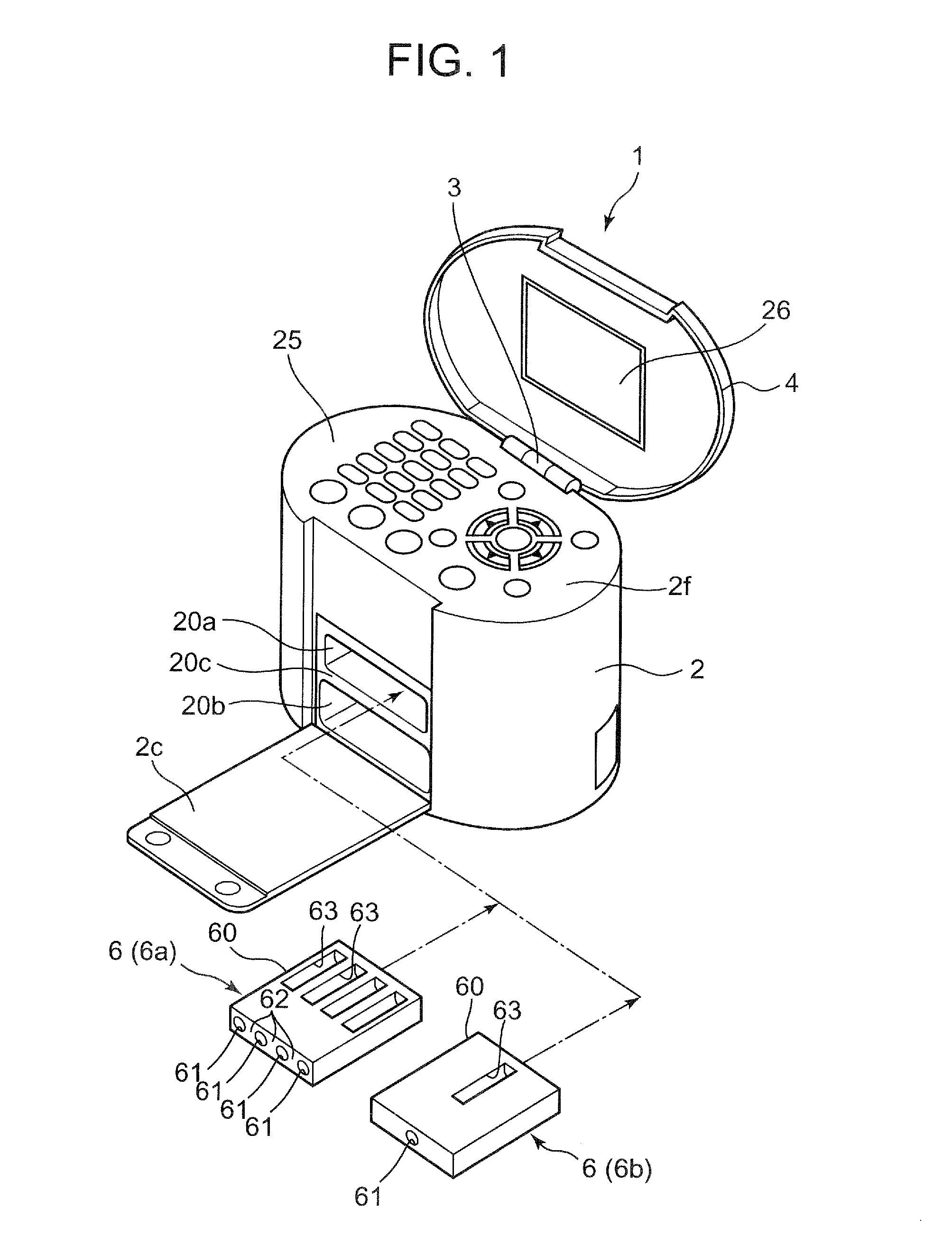
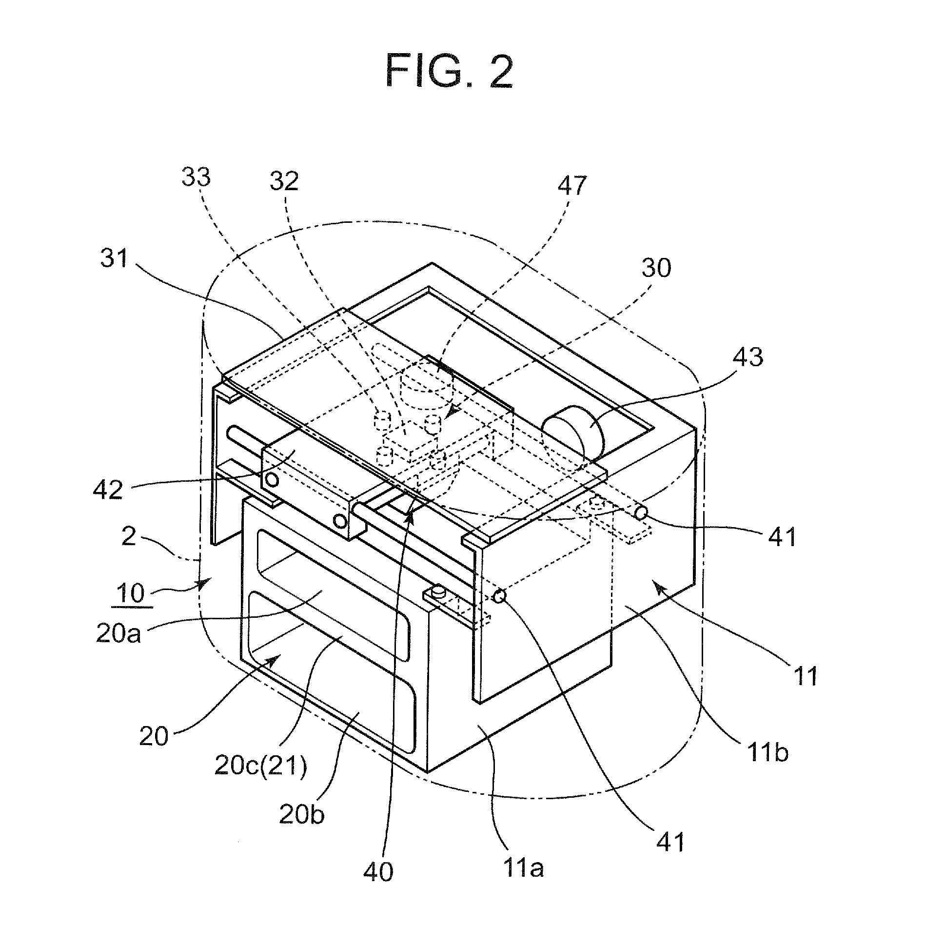
[0102]FIG. 1 is a perspective view showing an outside appearance of a nail print apparatus of the present embodiment and FIG. 2 is a perspective view showing an inner configuration of the nail print apparatus.

[0103]The nail print apparatus 1 of the present embodiment is an apparatus which can generate a nail chip 70 (see FIG. 25, etc.) which can be attached to a nail section of a finger. As shown in FIG. 1, the nail print apparatus 1 includes, for example, a case main body 2, a cover 4, a print apparatus main body 10 including, for example, a first finger inserting section 20a which is a finger inserting section in which a finger (target finger U1) corresponding to a nail which is a target of collection of information necessary to generate the nail chip 70 is inserted, a finger holding member 6 configured so as to be able to be inserted in and removed...

second embodiment

[0233]The second embodiment of the nail print apparatus of the present invention is described with reference to FIG. 30 to FIG. 48.

[0234]The nail print apparatus of the second embodiment has an inner configuration similar to the nail print apparatus of the first embodiment shown in FIG. 1 and the nail print apparatus shown in FIG. 2. Therefore, the portions with the same configuration are omitted.

[0235]In the present embodiment, the photographing section 30 functions as a first image obtaining section which illuminates the target finger U of other person a (in other words a first person) with the illuminating lamp 33, photographs the target finger U with the camera 32, and obtains the finger image including nail images Ga1 to Ga5 (see FIG. 30) of the plurality of nail sections T of the other person a (first person).

[0236]The photographing section 30 also functions as a second image obtaining section which illuminates the target finger U of the user (in other words, a second person) ...

third embodiment

[0323]Next, the third embodiment of the nail print apparatus of the present embodiment is described with reference to FIG. 49. The present embodiment is different from the second embodiment regarding only the configuration of the first image obtaining section which obtains a finger image including a nail image of the nail section of the other person (first person). Therefore, the points different from the second embodiment are described below.

[0324]FIG. 49 is a perspective view showing an outer appearance of a nail print apparatus of the present embodiment.

[0325]In the present embodiment, a medium inserting opening 27 in which a storage medium 9 such as a memory card, etc. can be inserted from outside is provided on the upper section of the case main body 2 of the nail print apparatus. The print apparatus main body 10 included inside the case main body 2 is provided with a connecting section (not illustrated) which can be connected to a terminal section 91 of the storage medium 9 in...


PUM


Abstract

Disclosed is a nail print apparatus including: a photographing section which photographs a plurality of fingers and a nail section of each finger to obtain a finger image; a finger type detecting section which detects a type of each finger from the finger image; a first storage controlling section which stores the type of finger detected by the finger type detecting section corresponded with the nail image; a design specifying section which receives specification of a design image to be printed; a second storage controlling section which stores the design image specified on the design specifying section; a combined nail image generating section which combines the design image with the nail image for each type of finger to generate a combined nail image; and a print controlling section which controls printing of the combined nail image on the nail chip sheet.

Description

BACKGROUND OF THE INVENTION[0001]1. Field of the Invention[0002]The present invention relates to a nail print apparatus and a print controlling method.[0003]2. Description of the Related Art[0004]Conventionally, there is known a nail print apparatus in order to print a design image such as character or picture on a finger nail of a person as described in Japanese Unexamined Patent Application Publication (Translation of PCT Application) No. 2003-534083.[0005]A nail print apparatus is an apparatus which photographs a nail on which printing is performed with a photographing section to detect a nail area which is to be a print target and a design image selected by a user is printed using a print head, etc. of an ink jet method on the detected nail area.[0006]By using such apparatus, nail print can be easily enjoyed without going to a nail salon, etc.[0007]However, there is a problem that, as in conventional nail print apparatuses where printing is performed by spraying ink directly on ...

Claims


Application Information

Patent Timeline
IPC IPC(8): B41J3/00G03B29/00
CPCB41J3/407B41J11/008A45D2029/005A45D34/04G03B29/00
Inventor MURATA, YOSHIYUKI
Owner CASIO COMPUTER CO LTD
Why Eureka
Try Eureka