Non-Interference Field-of-view Support Apparatus for a Panoramic Facial Sensor

a technology of facial sensor and support apparatus, which is applied in the direction of two-way working system, television system, instruments, etc., can solve the problems of fan's camera only looking outward from the user, not being able to facilitate face-to-face video teleconferencing, and not being designed for face-to-face video capture devices, etc., to facilitate interaction, facilitate presentation, and reduce visual presence

Active Publication Date: 2012-05-10
VIRTUAL VIDEO BY RITCHEY LLC
View PDF3 Cites 137 Cited by
  • Summary
  • Abstract
  • Description
  • Claims
  • Application Information

AI Technical Summary

Benefits of technology

[0007]The present invention is directed at a providing a personal mobile hands-free support apparatus with an adjustable armature and extension mechanism positions and holds a spherical field-of-view image and audio sensor assembly located at its distal end in front of a users face such that the user's fine focus field-of-view of the foreground is not blocked by the mast or the sensor assembly is provided. Manual or automated mechanisms rotate and extend the armature with assembly into position for mobile face-to-face panoramic hands-free video teleconferencing or logging. The portable host electronic device, such as a personal digital assistant or cell phone, communicates with the apparatus circuitry, servos, spherical image sensor, audio system, eye and head tracking, and other optional sensor systems to interactively and in an automated manner command and control the apparatus to hide and reduce the visual presence of the sensor assembly in front of the users face for the user and to onlookers in front of the user. Optionally, in several embodiments of the invention a display is mounted on the armature and sensor assembly to hide and conceal the sensor assembly and armature and to provide audio-visual information to the wearer of the apparatus.
[0008]There is a continuing need to capture a frontal view of the users face while the user is on the move so that the user can conduct mobile video teleconferences. There is also a need for the audience at the far end of the teleconference to see what the user is looking at or look independently at the environment the user is occupying. There is also a need to provide a device that allows portable hands-free interaction with a portable digital device, like a PDA or cell phone. There is also a need to record the user's facial reaction to events while simultaneously recording events taking place in the environment the user is occupying. There is also a need for a support device with a portable facial sensor that is responsive to automated wake up features of a portable device. There is also a need for a support device with a facial sensor located directly in front of the face of user that automatically positions itself to in response to the field-of-view and focus of the eyes of the user. There is also a need for a device that masks the device in front of the users face from the user and onlookers. There is also a need to provide a support device that does not block the peripheral view of the user w

Problems solved by technology

Devices for face-to-face video capture have not been designed to hold a sensor apparatus directly in front of the face of the user without obstructing the user's fine focus field-of-view.
A limitation of Fan is that Fan's camera only looks outward from the users head mounted support and does not facilitate face-to-face video teleconferencing.
Another limitation of Biocca is that the head mounted support armature that holds a mirror or a camera blocks the peripheral FOV of the user who is wearing the support device.
A l

Method used


Image

  • Non-Interference Field-of-view Support Apparatus for a Panoramic Facial Sensor
  • Non-Interference Field-of-view Support Apparatus for a Panoramic Facial Sensor
  • Non-Interference Field-of-view Support Apparatus for a Panoramic Facial Sensor

Examples


second embodiment

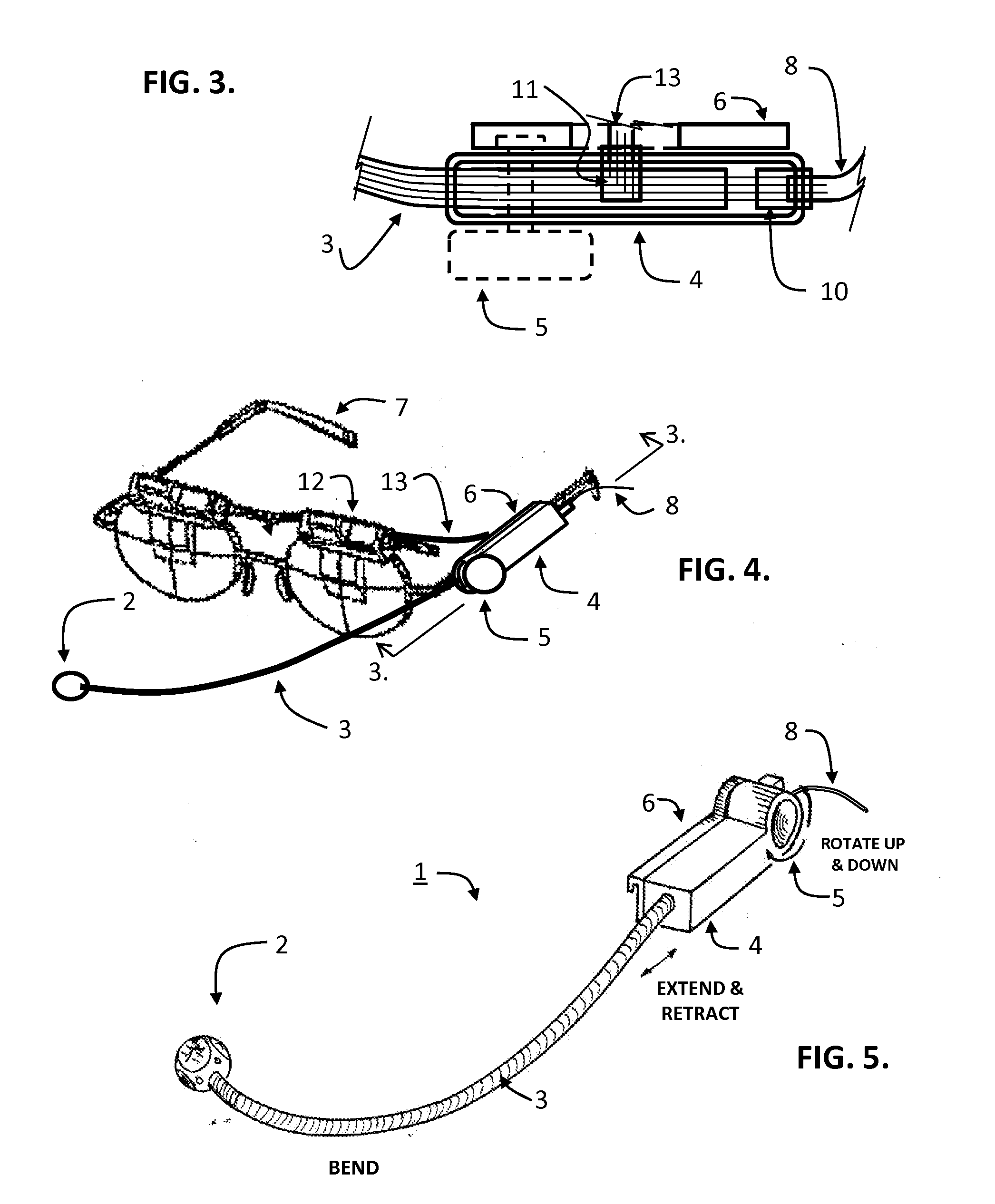
[0064]FIG. 5 is a perspective view of the support device apparatus 1 for holding a spherical field-of-coverage image and audio sensor assembly 2 in place according to the present invention. The armature comprises a flexible gooseneck material well known to those in the lighting and borescope industry. Wiring running from the sensor 2, through the hollow stem of the gooseneck armature 3, and into the support housing 4 continues onward through a flexible cable 8 that runs to a host electronic device. The support housing 4 includes a mechanism that raises and lowers the armature 3 and sensor assembly 2. Designation A1 indicate the rotational direction of the motorized hinge. Designation A2 indicates the direction of the armature extension. The range of the extension will typically vary between 15.24 centimeters to 30.48 centimeters to accommodate the eyes of the user at a comfortable in focus reading distance. Those skilled in the art will realize there are numerous types of miniature ...

third embodiment

[0065]In addition to the functionality shown in FIG. 5, FIG. 6a -6b are perspective views of the support device apparatus 1 in which the support housing 4 includes a mechanism that extends and retracts the armature 3 and sensor 2 forward and backwards as indicated by the arrows A2. Arrows A2 indicate the extension and retraction direction of the armature and sensor. FIG. 6a shows the armature in the extended position. FIG. 6b shows the armature in the retracted position. In the retracted position the proximal end of the armature 3 is stowed in a protective extension tube 14 that is constructed into and integrated with the armature support housing 4. The tube may be configured to wrap around the back of the head of the user in order to assist in holding the support device apparatus 1. The proximal end of the armature extends into the housing and may extend out of the back side of the housing when the armature is retraced. The proximal end of the armature is held tight when extended b...


PUM


Abstract

A support apparatus with adjustable mechanisms hold a spherical field-of-regard image and audio sensor assembly located at its distal end in front of a users face such that the user's fine focus field-of-view of the foreground is not blocked by the mast or the sensor assembly. Automated mechanisms rotate and extend the armature and sensor assembly into position for face-to-face panoramic hands-free video teleconferencing, gaming, or logging. A portable wired or wireless host electronic device with a personal assistant application and sensor correlation system interactively communicates with support apparatus circuitry and servos, imagery, audio, eye and ROI tracking, neural, and user input and feedback systems to orchestrate responses to a local or remote user. A sensor assembly includes a VLSIC multi-ROI processing system with integrated camera and display that hides the assembly and provides information to a user or onlooker.

Description

CROSS-REFERENCE TO RELATED APPLICATIONS[0001]This continuation-in-part patent application claims the benefit of, and priority to, all current pending United States Non-Provisional patent applications that specifically includes Ser. No. 11 / 354,779 filed Feb. 15, 2006 and published as United States Patent Publication No. 2007 / 0002131 entitled Dynamic Interactive Region-of-Interest Panoramic / Three-Dimensional Immersive Communications System and Method; U.S. patent application Ser. No. 11 / 830,637 filed Jul. 30, 2005, and published on Jan. 31, 2008 as United States Patent Publication No. 2008 / 0024594 A1 entitled Panoramic Image-Based Virtual Reality / Telepresence Audio-Visual System and Method; filed on the present inventors behalf by Frank. C. Nicholas, Cardinal Law Group, 1603 Orrington, Suite 2000, Evanston, Ill. 60201, Ph. (847) 905-7111. And claims the benefit of and priority to U.S. patent application Ser. No. 12 / 266,308 filed Nov. 6, 2007 and published as United States Patent Publi...

Claims


Application Information

Patent Timeline
IPC IPC(8): H04N7/14H04N7/00
CPCH04N5/2254H04N5/2259H04N5/23238H04N7/142H04N21/4305G02B2027/0187G02B27/017G02B2027/0123G02B2027/0156G02B2027/0138G02B2027/014H04N2007/145H04N23/58H04N23/50H04N23/61H04N23/698G10L15/26G02B27/0093G02B27/0172G02B27/0176G02B27/0179G02B2027/0178G06F3/013G06F3/015H04N7/15
Inventor RITCHEY, KENNETH IRARITCHEY, KURTIS JOHN
Owner VIRTUAL VIDEO BY RITCHEY LLC
Why Eureka
Try Eureka