System and method for detecting analytes present in a gas sample

a gas sample and detection system technology, applied in the direction of material analysis, instrumentation, spectral investigation, etc., can solve the problems of spatial heterogeneity, detection device, and inability to define the general shape of the material, and achieve the effect of increasing the viscosity of the sol

Active Publication Date: 2012-05-10
COMMISSARIAT A LENERGIE ATOMIQUE ET AUX ENERGIES ALTERNATIVES
View PDF7 Cites 8 Cited by
  • Summary
  • Abstract
  • Description
  • Claims
  • Application Information

AI Technical Summary

Benefits of technology

[0047]Said material is preferably microporous or mesoporous. Microporous materials have an average pore size of substantially less than 20 Å, mesoporous materials have an average pore size comprised between 20 Å and 500 Å, macroporous materials having an average pore size of more than 500 Å, for example comprised between 50 nm and 100 μm. Preferably the material applied in the invention is microporous.
[0048]Said porous material may be a sol-gel. By <> or <<sol-gel material>>, both expressions being equivalent and interchangeable, is meant a material obtained by a sol-gel method consisting of using as precursors either identical or different metal alkoxides of formula M(OR)n(R′)m wherein M is a metal such as silicon, R and R′ represent an alkyl group and m and n are integers with m+n=4, 2≦n≦4 and 0≦m≦2. The sol-gel materials are generally prepared in a solvent, which is preferably miscible with water and may be evaporated under mild conditions, in which the precursors are soluble. In the case of silicon alkoxides, mention may notably be made of alcohols, such as methanol, ethanol; ethers such as diethyl ether and tetrahydrofurane; chlorinated solvents, such as chloroform, CH2Cl2, C2H5Cl2 or other aprotic solvents such as CH3CN, acetone, methylethylketone, or dioxane or protic solvents such as acetic acid, formamide. In the presence of water, hydrolysis of the alkoxide groups (—OR) occurs and the latter are transformed into silanol groups (Si—OH) which condense by forming siloxane groups (Si—O—Si). Small particles with a size generally of less than 1 nm are then formed. They aggregate and form lacunate clusters in suspension in the liquid: this is the sol. As polycondensation continues over time, the viscosity of the sol increases until it gels: the sol becomes a gel. A solid sol-gel material is obtained by drying the gel. During this step, the residual and interstitial solvents escape from the formed polymeric lattice and evaporate which causes contraction of the material. A final material is obtained, the volume of which is reduced as compared with the volume occupied by the sol. The sol therefore corresponds to a solution from which the material of interest to be deposited, in this case the sol-gel material, is obtained.

Problems solved by technology

However, this detection device has a certain number of drawbacks.
Thus, the material used in this example of the prior art is a sol-gel material deposited with the known technique of >, which does not allow delimitation of the general shape of the material.
The response signal to the light excitation, received by the optical collector, is therefore spatially heterogeneous, which is detrimental to the resolution of the detector.
These areas therefore do not respond or only very little to the light excitation which is sent to them, thereby decreasing the resolution of the detector.
Finally, the detector has a sensitivity which tends to degrade over time.
Indeed, the probe molecules which have reacted with an analyte and have responded by absorbance or fluorescence to the light excitation, no longer respond to subsequent light excitations.
Also, the amount of probe molecules capable of reacting with the analyte and responding to a light excitation decreases over time, thus decreasing the sensitivity of the detector.
However, this detection system has a particularly limited operating time.
On the other hand, as each detection area is dedicated to a single category of analytes of interest, when the probe molecules of a same detection area have all reacted with the relevant analyte, the detection of this analyte is no longer possible.

Method used


Image

  • System and method for detecting analytes present in a gas sample
  • System and method for detecting analytes present in a gas sample
  • System and method for detecting analytes present in a gas sample

Examples


Embodiment Construction

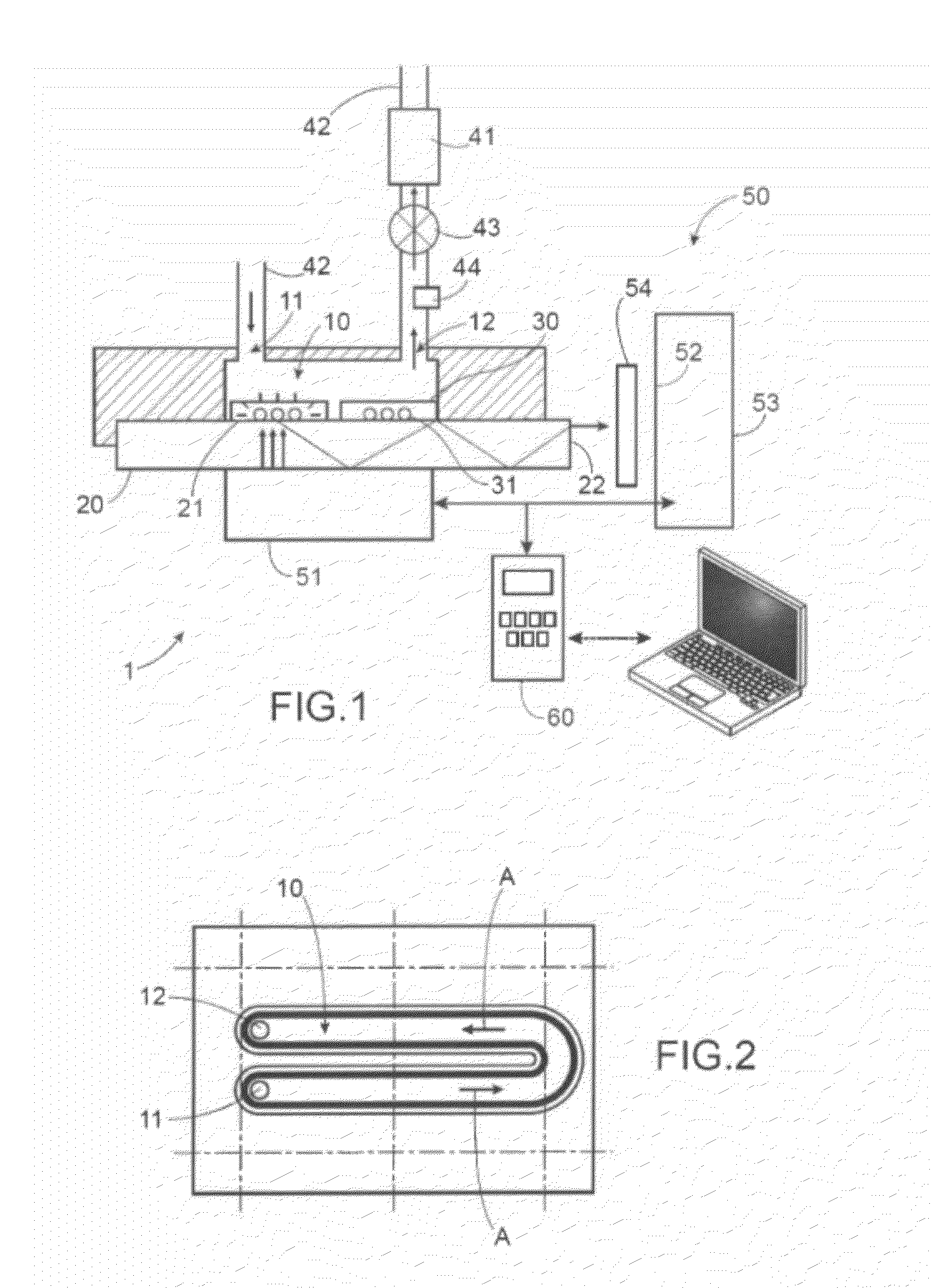
[0096]In FIG. 1 a system 1 is illustrated for detecting analytes of interest present in a gas sample according to a preferred embodiment of the invention.

[0097]The detector 1 comprises a fluidic chamber 10 provided with a gas inlet orifice 11 and a gas outlet orifice 12. Both of these orifices 11, 12 are positioned so as to define inside the fluidic chamber and cooperating with the interior walls of the latter, a fluidic flow path for the gas sample.

[0098]As shown in FIG. 2, the fluidic chamber 10 may extend in a rectilinear way and include a curved portion. The direction of the fluidic path is given by the arrow A.

[0099]The fluidic chamber 10 comprises a planar solid substrate 20, a surface 21 of which forms at least partly one of the interior walls of the fluidic chamber 10 (FIG. 1). The substrate 20 may be a microscope glass slide.

[0100]The substrate 20 is here transparent or translucent, and thus lets through light.

[0101]On said surface 21 of the substrate 20 is positioned a lay...


PUM


Abstract

The invention relates to a system (1) for detecting analytes of interest present in a gas sample. The detection system comprises a layer (30) of porous material positioned along the fluidic flow path for the gas, the material containing probe molecules capable of reacting with the analyte of interest. The detection system also comprises an optical device (50) capable of successively detecting a change in the spectral properties of the probe molecules at different detection areas (32) of the porous material layer (30).

Description

TECHNICAL FIELD[0001]The present invention relates to the general field of detection of analytes of interest present in a gas sample. These analytes may be chemical, biological or biochemical compounds present in a gas environment.STATE OF THE PRIOR ART[0002]In many fields, it is sought to produce, analyze a gas environment or a gas sample with the purpose of for example detecting chemical, biological or biochemical compounds present.[0003]This is notably the case of the field of clinical diagnosis, where it may be sought to detect bio-markers of diseases in breath samples of persons, of monitoring of the environment, in particular of the quality of air, or of the field for monitoring industrial activities, for example for analyzing industrial effluents, or monitoring of personnel exposed to volatile organic compounds.[0004]Patent application WO 2007 / 031657, notably filed in the name of the applicant, describes a system for detecting analytes of interest present in a gas sample. Thi...

Claims


Application Information

Patent Timeline
Patent Type & Authority Applications(United States)
IPC IPC(8): G01J3/443
CPCG01N21/05G01N21/783G01N2021/0346G01N2021/7786G01N2021/7783
Inventor VIGNOUD, SEVERINEDESCAMPS, MICHAELPERRAUT, FRANCOISPLANAT-CHRETIEN, ANNESCHULTZ, EMMANUELLE
Owner COMMISSARIAT A LENERGIE ATOMIQUE ET AUX ENERGIES ALTERNATIVES
Why Eureka
Try Eureka