Heat dissipation means for increasing power density in enclosed equipment

a technology of heat dissipation and equipment, which is applied in the direction of electrical apparatus construction details, electrical apparatus casings/cabinets/drawers, instruments, etc., can solve the problems of direct affecting the required size of piu and/or the size of phase-conductors, limiting the overall thermal performance and managing the rise in temperature of the busway system

Active Publication Date: 2012-05-10
SCHNEIDER ELECTRIC USA INC
View PDF15 Cites 24 Cited by
  • Summary
  • Abstract
  • Description
  • Claims
  • Application Information

AI Technical Summary

Benefits of technology

[0005]The present disclosure is directed to providing a thermally efficient electrical enclosure, such as, for example, a thermally efficient plug-in or bolt-on unit for use with a busway system. The thermally efficient electrical enclosure preferably includes a substantially air-tight exterior enclosure with one or more parallel busbars located therein for conducting one or more phases of electricity. The thermally efficient electrical enclosure transf

Problems solved by technology

A common problem in busway systems is the management of the rise in temperature of the busway system within the PIUs.
A rise in temperature within the PIUs limits the overall thermal performance of the busway system, which directly affects the required size of the PIU and/or the size of the phase-conductors.
Using larger phase-conductors to accommodate for the rise in temperature at the PIUs i

Method used


Image

  • Heat dissipation means for increasing power density in enclosed equipment
  • Heat dissipation means for increasing power density in enclosed equipment
  • Heat dissipation means for increasing power density in enclosed equipment

Examples


Embodiment Construction

[0022]Although the present disclosure will be described in connection with certain aspects and / or embodiments, it will be understood that the present disclosure is not limited to those particular aspects and / or embodiments. On the contrary, the present disclosure is intended to cover all alternatives, modifications, and equivalent arrangements as may be included within the spirit and scope of the invention as defined by the appended claims.

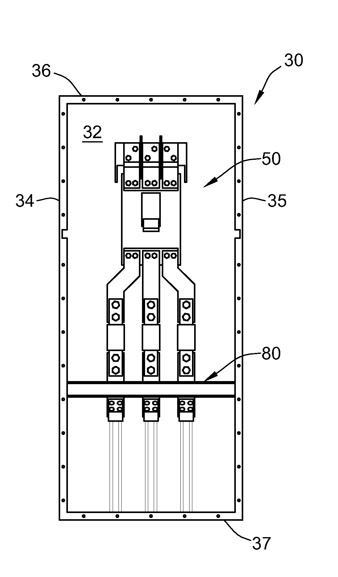
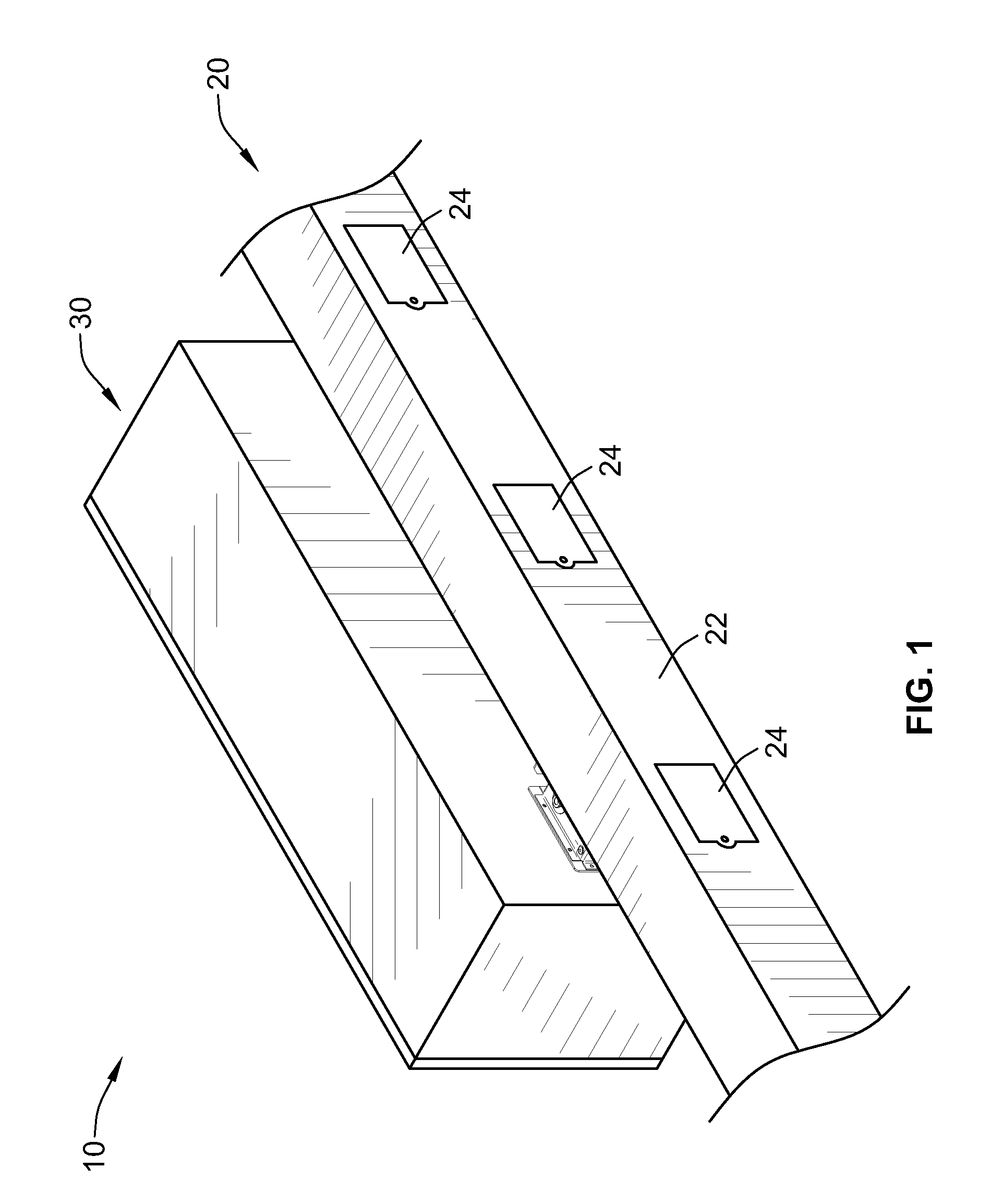
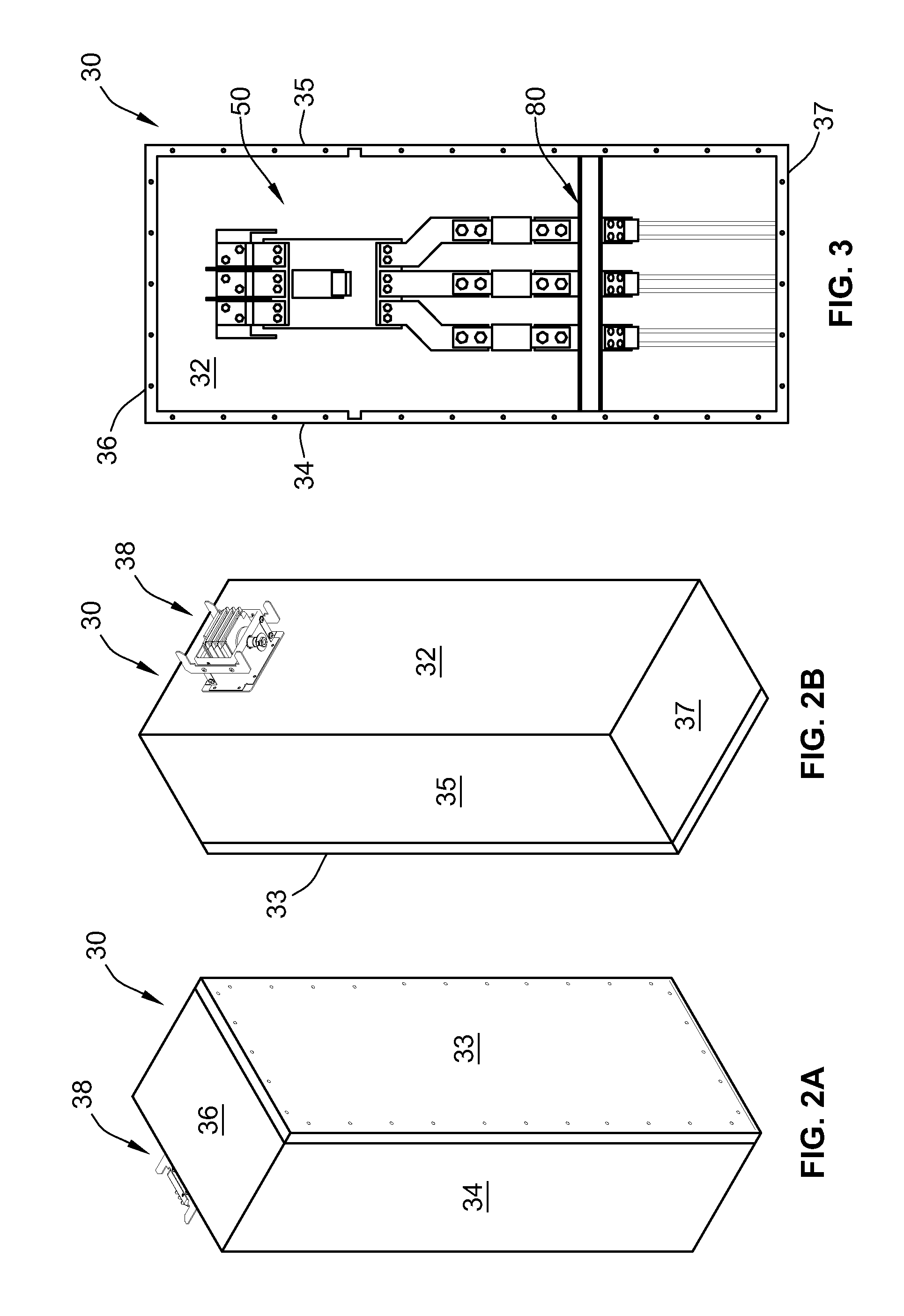
[0023]Referring to FIG. 1, an exemplary busway system 10 is shown. The busway system 10 includes a busway 20, and a thermally efficient electrical enclosure 30 coupled thereto. In the illustrated example, the busway 20 is a three-pole busway, which can also be referred to as a three-phase busway. The busway 20 includes a busway housing 22 and three phase-conductors (not shown) for distributing three separate phases of electricity between a source of electrical current and a load. The busway housing 22 includes a plurality of plug-in connection sit...


PUM


Abstract

A thermally efficient electrical enclosure includes a busbar, a metallic heat sink, and an electrical insulator. The busbar is positioned entirely within the enclosure and electrically insulated from the enclosure. The metallic heat sink is attached to a wall of the enclosure. The electrical insulator physically contacts the busbar and is at least partially wrapped around at least two non-parallel surfaces of a portion of the metallic heat sink such that the metallic heat sink is electrically insulated from the busbar. The metallic heat sink is configured to transfer thermal energy or heat from the busbar to the enclosure such that the thermal energy is lost or transferred to the surrounding environment, which reduces the temperature of the busbar and the amount of copper needed for the busbar without reducing the rating of the enclosure.

Description

FIELD OF THE INVENTION[0001]The present invention relates generally to electrical distribution equipment and, more particularly, to thermally efficient electrical enclosures.BACKGROUND OF THE INVENTION[0002]A busway system typically includes one or more busways, one or more busway joint packs, and multiple plug-in units (PIUs). Each busway joint pack is used to physically and electrically connect two sections of busway or two sets of busway together. Various PIUs having electrical components can be directly connected to one or more plug-in connection sites spaced along the busways to draw power. Each PIU includes one or more phase-conductors and a housing. For example, in a three-phase system, the PIU can include three live phase-conductors or three live phase-conductors and one neutral-conductor, depending on the type of system architecture being employed.[0003]A common problem in busway systems is the management of the rise in temperature of the busway system within the PIUs. A ri...

Claims


Application Information

Patent Timeline
IPC IPC(8): H02B1/56H05K7/20
CPCH02G5/10H02B1/56
Inventor PERALTA, HILDEGARDSALAS, EZEQUIELDIAZ, MAURICIO
Owner SCHNEIDER ELECTRIC USA INC
Why Eureka
Try Eureka