
Proportional valve having an improved sealing seat

a technology of proportional valves and sealing seats, which is applied in the direction of valve housings, valve operating means/release devices, machines/engines, etc., can solve the problems of unwanted leakage, inability to improve the seal on the valve seat, and inability to leakage, so as to improve the tightness of the valve seat, improve the sealing effect, and improve the sealing

Inactive Publication Date: 2012-05-10
ROBERT BOSCH GMBH
View PDF12 Cites 13 Cited by
  • Summary
  • Abstract
  • Description
  • Claims
  • Application Information

AI Technical Summary

Benefits of technology

[0005]A proportional valve according to an example embodiment of the present invention for controlling a gaseous medium may have the advantage that an improved tightness on the valve seat is ensured. In particular, slight tilting of a closing element may be compensated. In accordance with the present invention, this may be achieved by the fact that the closing element is articulated with the aid of an articulated support. Compensating movements of the closing element may thus be carried out via the articulated support. This makes it possible for a sealing element to always rest planarly on a valve seat. In particular, an effective sealing of gaseous hydrogen, which has a very small molecule size, is made possible thereby. The valve is preferably used to supply hydrogen to a fuel cell.
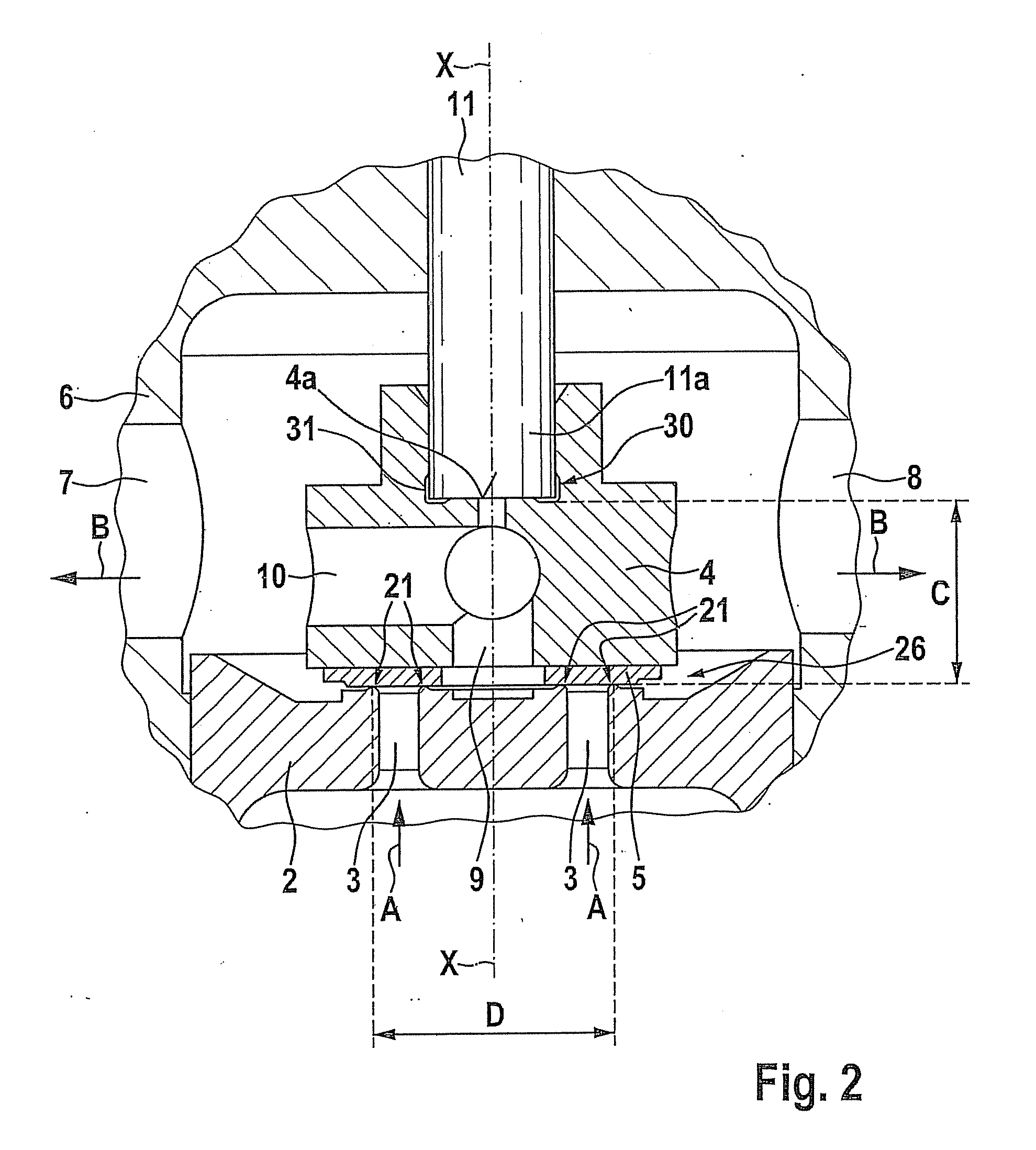
[0006]The example proportional valve according to the present invention preferably includes a component which has a pin-shaped end, in particular a pin, and the articulated support is situated between the pin-shaped end and the closing element. This makes it possible to integrate the articulated support into a connection between the pin-shaped end and the closing element.
[0009]To allow for a preferably compact configuration, the pin-shaped end is preferably situated in a recess in the closing element. This makes it possible, in particular, to reduce an axial length of the proportional valve.
[0012]The closing element is preferably articulated on an actuator and captively situated thereon. The actuator is preferably a magnet armature. This enables a particularly compact configuration to be implemented. In particular, the actuator preferably includes a holding device, a form-locked connection being provided between the holding device and the closing element. The holding device is preferably a holding bushing. This holding bushing preferably projects over a free end of the actuator and forms a receiving chamber for accommodating the closing element. The form-locked connection between the holding device and the closing element makes it possible, in particular, to transmit axial forces from the actuator to the closing element.
[0014]In particular, the sealing element provides a sealing action on a sealing diameter on a valve seat, the closing element having a height in an axial direction, i.e., a direction of movement, for opening and / or closing the proportional valve, and a ratio of the sealing diameter to the height of the sealing element being greater than 1. A ratio of greater than 1 between the sealing element and the height of the closing element ensures that the closing element is able to align itself by sliding on the valve seat, and no self-retention occurs.
[0017]According to a further preferred embodiment of the present invention, the proportional valve furthermore has a stop which delimits a tilting movement of the closing element. Excessive tilting movements are thereby avoided, in particular when the proportional valve is open, which could result in flow fluctuations during operation due to a movement of the closing element. Since the proportional valve is open in nearly all operating positions during operation of a fuel cell, the articulated support should preferably allow a maximum clearance of 0.03 mm.

Problems solved by technology

Even minimal tilting of a closing element may result in unwanted leakages.
However, this valve is not designed as a proportional valve but rather as an injection timing valve, and it provides no indication of ways to improve a seal on the valve seat.
Too great a radial runout would furthermore cause a reduction in an overlap between the valve seat and the closing element, which could result in impermissible leakage.

Method used


Image

  • Proportional valve having an improved sealing seat
  • Proportional valve having an improved sealing seat
  • Proportional valve having an improved sealing seat

Examples


Embodiment Construction

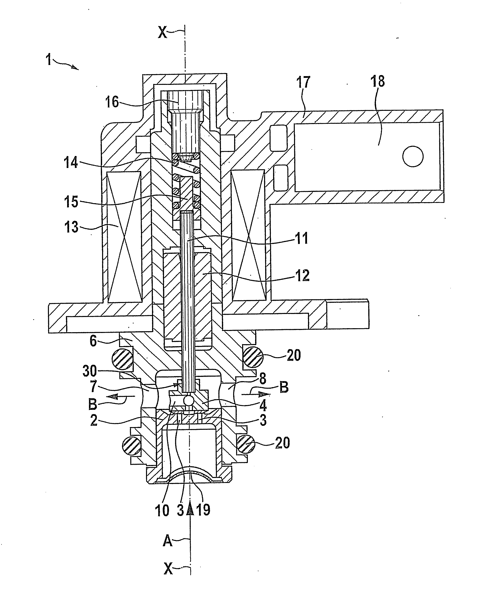
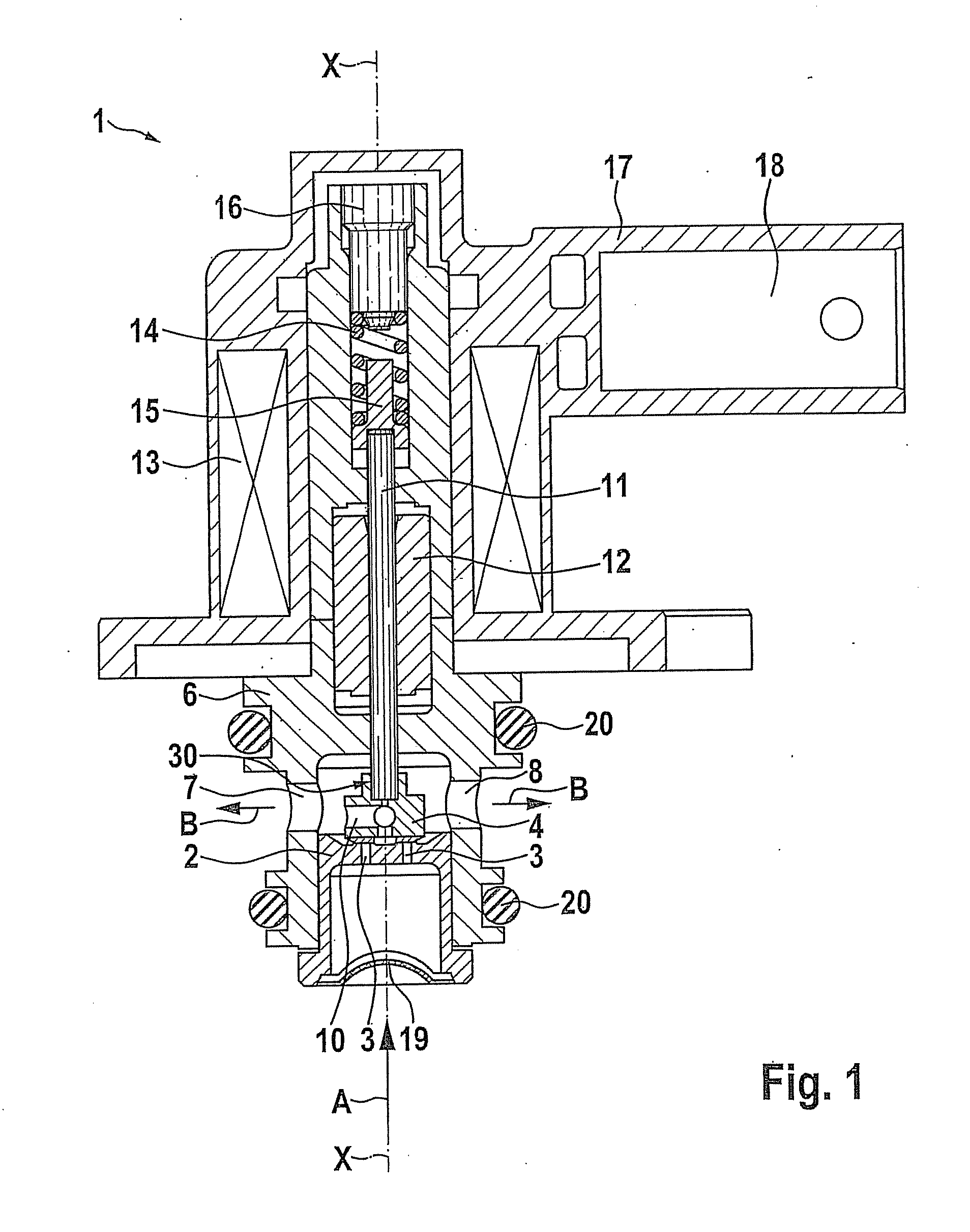
[0025]A proportional valve 1 for controlling a gaseous medium is described in detail below with reference to FIGS. 1 and 2. Proportional valve 1 illustrated in the figures is used to control gaseous hydrogen which is supplied, for example, to a fuel cell in a vehicle.

[0026]As is shown in FIG. 1, proportional valve 1 includes a valve housing 6 which has a magnet armature 12, a solenoid coil 13 and a pin 11 which is connected to magnet armature 12. A closing spring 14 is connected to pin 11 via a spring holder 15. Reference numeral 16 identifies an adjusting bolt for adjusting a restoring force of closing spring 14. Solenoid coil 13 is fixed in a plastic overmold 17 on valve housing 6. A plug connector 18 is provided on the side of proportional valve 1. A closing element 4 is situated on pin-shaped end 11a of pin 11, which is located opposite closing spring 14. Closing element 4 closes pass-through openings 3 which are provided in a nozzle body 2. Pass-through openings 3 are situated ...


PUM

PropertyMeasurementUnit
distanceaaaaaaaaaa
diameteraaaaaaaaaa
distanceaaaaaaaaaa

Abstract

A proportional valve for controlling a gaseous medium, in particular hydrogen, including a nozzle body which has at least one pass-through opening, a closing element which releases and closes the pass-through opening on a valve seat, and an elastic sealing element, which provides a seal on the valve seat, the closing element being articulated with the aid of an articulated support.

Description

CROSS REFERENCE [0001]The present application claims the benefit under 35 U.S.C. §119 of German Patent Application No. DE 102010043619.4 filed on Nov. 9, 2010, which is expressly incorporated herein by reference in its entirety.FIELD OF THE INVENTION [0002]The present invention relates to a proportional valve for controlling a gaseous medium, in particular hydrogen, and in particular for use in vehicles which have a fuel cell drive.BACKGROUND INFORMATION [0003]In the automotive sector, not only liquid fuels but also gaseous fuels will play an increasing role in the future. Hydrogen gas flows must be controlled, in particular in vehicles which have a fuel cell drive. In this case, the gas flows are no longer controlled discontinuously as in the injection of liquid fuels, but instead proportional valves are preferably used, which adjust an opening cross section of the valve as a function of a desired driving power.[0004]Due to the small molecule size of gaseous hydrogen, strict requir...

Claims


Application Information

Patent Timeline
Patent Type & Authority Applications(United States)
IPC IPC(8): H01M8/04F16K27/00
CPCF16K31/0655F16K31/10F02M21/0254F02M21/0266Y02T10/32Y02T10/30
Inventor STIER, HUBERTWILL, CHRISTIANILGNER, FRANK
Owner ROBERT BOSCH GMBH
Learn More