Vacuum Boost For Vehicle Braking

a technology for vehicle braking and vacuum boost, which is applied in the direction of combustion air/fuel air treatment, electric control, instruments, etc., can solve the problems achieve the effect of increasing engine rpm, increasing engine rpm, and increasing the vacuum of the intake manifold

Inactive Publication Date: 2012-05-10
FORD GLOBAL TECH LLC
View PDF6 Cites 21 Cited by
  • Summary
  • Abstract
  • Description
  • Claims
  • Application Information

AI Technical Summary

Benefits of technology

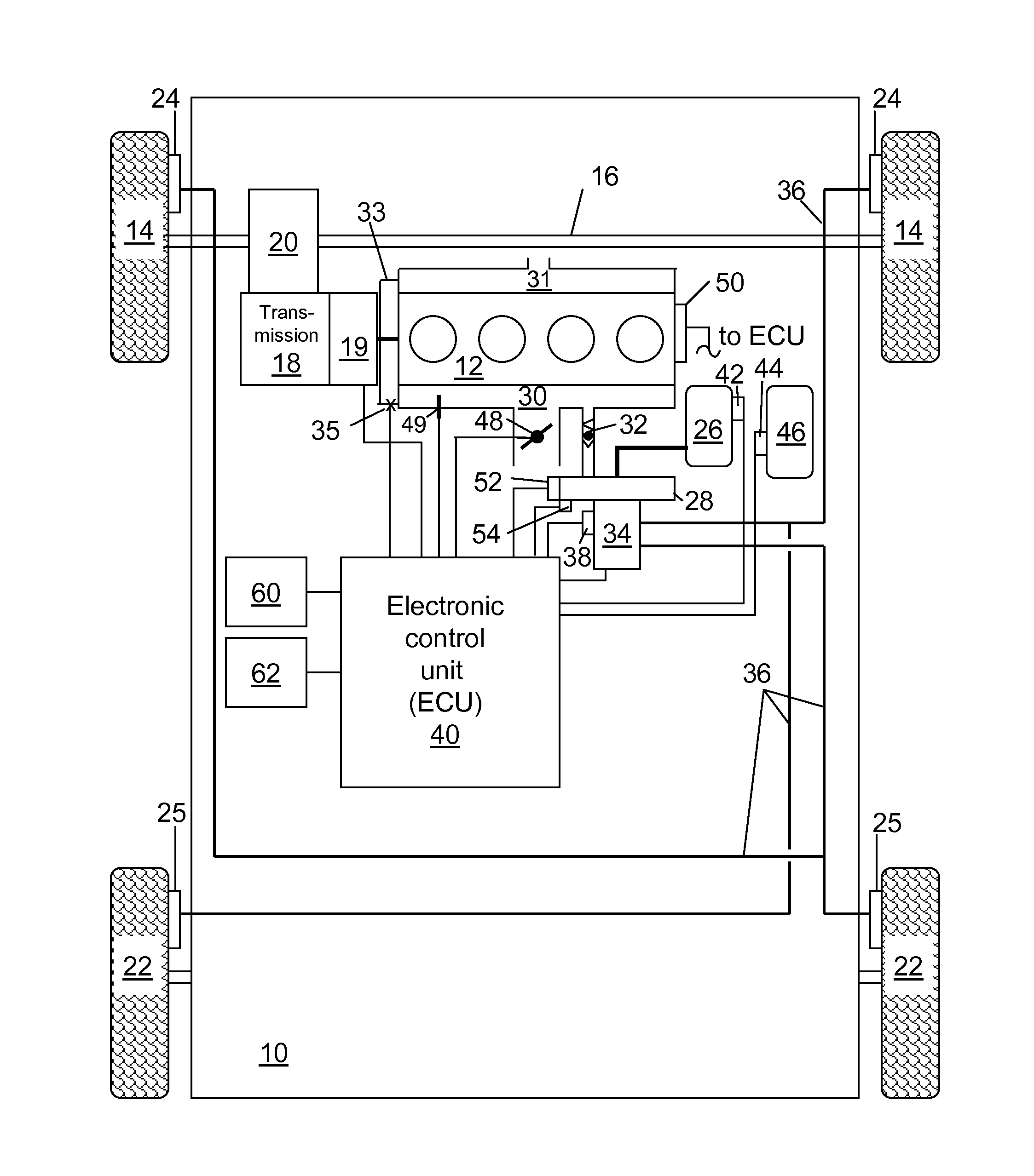
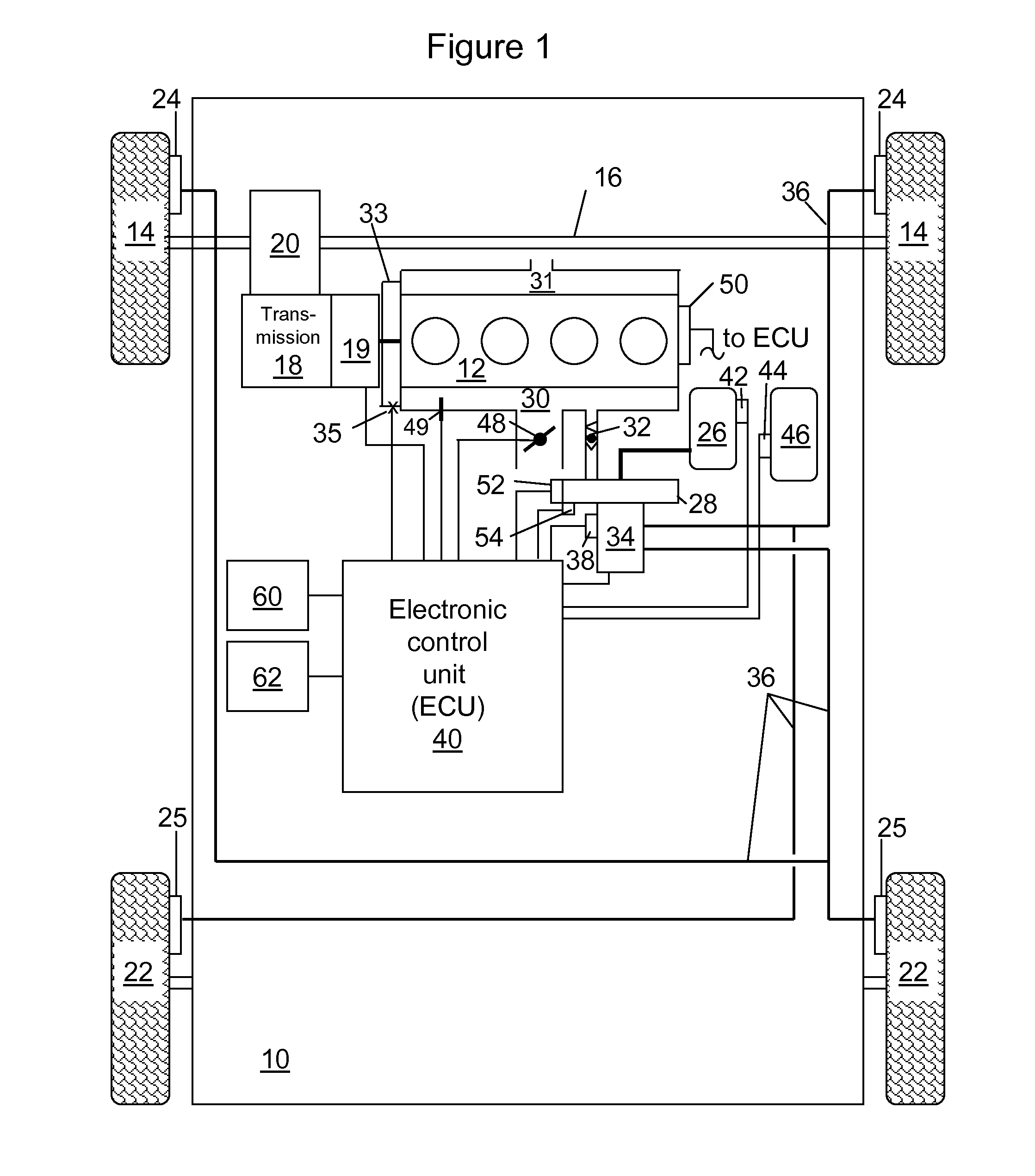
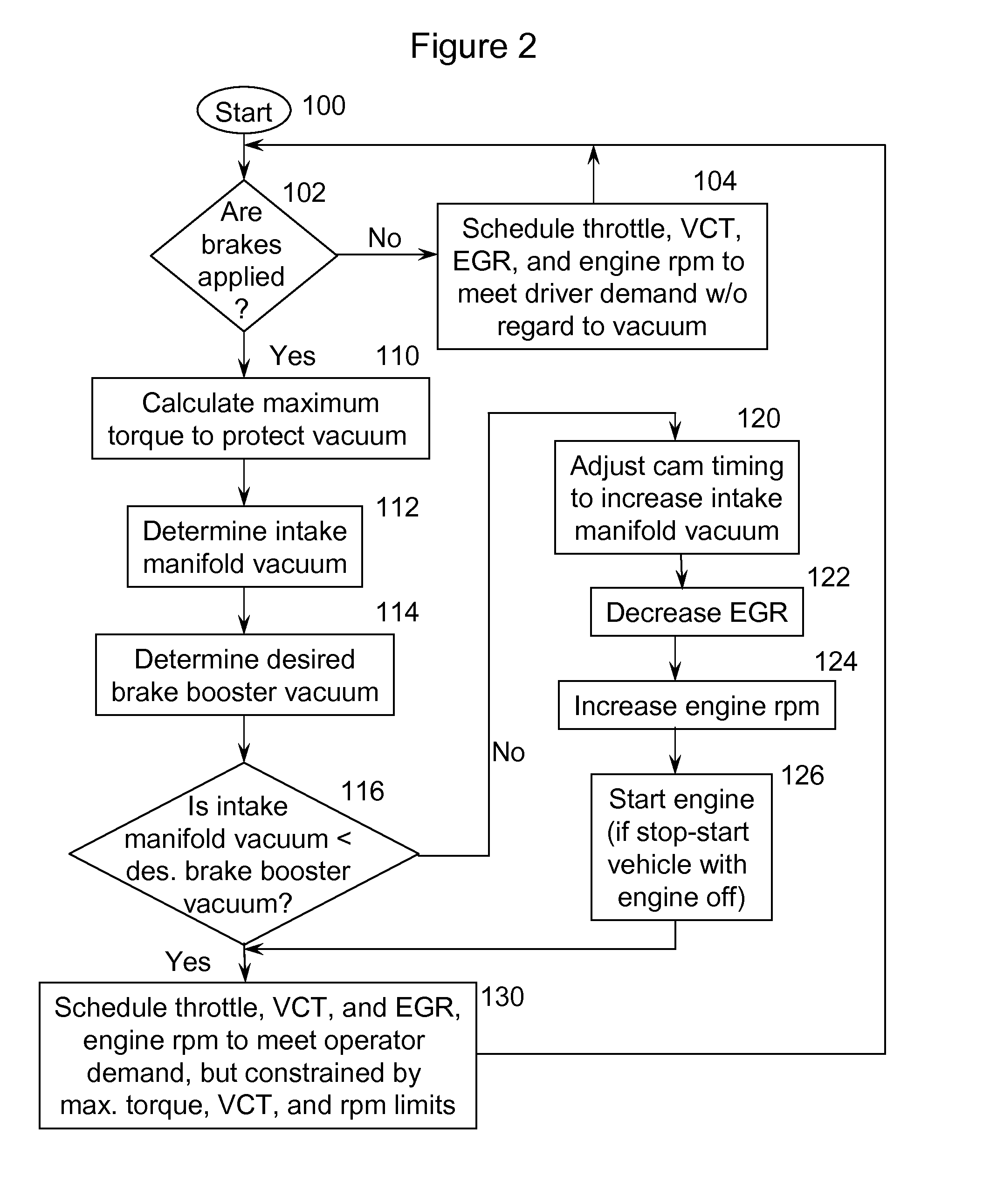
[0005]The present disclosure describes a system and method for ensuring vacuum boost for vehicle braking. The engine is control by: estimating a desired brake booster vacuum that ensures braking of the vehicle at a present operating condition of the vehicle, determining intake manifold vacuum, and increasing engine rpm when the manifold vacuum is less than the desired brake booster vacuum. In one alternative the engine is coupled to a continuously variable transmission (CVT) and the gear ratio in the CVT is adjusted in conjunction with the increasing engine rpm so that vehicle speed substantially equals a demand by an operator of the vehicle. In another alternative, the engine is coupled to an automatic transmission and the transmission is downshifted in conjunction with the increasing engine rpm so that vehicle speed substantially equals a demand by an operator the vehicle. In one alternative, the actual brake booster vacuum is determined and the engine rpm is increased in response to both the manifold vacuum level and the actual brake booster vacuum being less than the estimated brake booster vacuum. The actual brake booster vacuum is determined based on one of a signal from a vacuum sensor coupled to the brake booster and a model of brake booster vacuum. In vehicle including stop-start, i.e., ones in which the engine is shutoff and restarted independently of an operator request, the actual brake booster vacuum is estimated and the engine is restarted when the actual brake booster vacuum is less than the estimated brake booster vacuum. In engines with variable cam timing, cam timing is adjusted to a position which increases manifold vacuum when the manifold vacuum level is less than the estimated brake booster vacuum.
[0006]According to some embodiments in which the engine has variable cam timing, a desired brake booster vacuum that ensures braking of the vehicle at a present operating condition of the vehicle is estimated; intake manifold vacuum is determined, possibly by a sensor in the intake; and the intake manifold vacuum when the intake manifold vacuum is less than the estimated brake booster vacuum is increased. The intake manifold vacuum is increased by adjusting cam timing. If such measure is insufficient to provide the desired intake manifold vacuum, engine rpm is increased. In some embodiments, the actions taken to increase intake manifold vacuum are taken only when both the intake manifold vacuum and the actual brake booster vacuum are less than the desired brake booster vacuum. The intake manifold vacuum is further increased by increasing engine speed while adjusting a throttle valve in an engine intake toward a more closed position. The increasing the intake manifold vacuum is further based on a brake pedal coupled to the vehicle being depressed. Increasing the intake manifold vacuum, adjusting the cam timing, and increasing the engine speed are constrained to provide an operator demand for torque. In one embodiment a maximum engine torque is determined to protect vacuum by increasing the intake manifold vacuum, adjusting the cam timing, and increasing the engine speed, but such measures are constrained to provide the lower of an operator demand for torque and the maximum engine torque.
[0007]A vehicle is disclosed which includes wheels, brakes proximate the wheels, an internal combustion engine providing torque to the wheels via a drive train, a brake pedal, a brake booster fluidly coupled to an intake manifold of the engine and mechanically coupled to the brake pedal, a master cylinder mechanically coupled to the brake booster with the master cylinder having a hydraulic fluid and coupled to the brakes via hydraulic lines, and an electronic control unit electronically coupled to the engine. The ECU determines intake manifold vacuum, a desired brake booster vacuum that ensures braking of the vehicle at a present operating condition of the vehicle, and actual brake booster vacuum. The ECU commands the engine to increase manifold vacuum when both the intake manifold vacuum and the actual brake booster vacuum are less than the desired brake booster vacuum. In engine with a variable cam timing system coupled to the engine, the increase in intake manifold vacuum includes adjusting cam timing. The intake manifold vacuum is increased by the ECU simultaneously increasing engine speed and adjusting a throttle valve in the intake manifold to a more closed position. The actual brake booster vacuum is based on a signal from a vacuum sensor disposed in the brake booster. In engines in which the ECU commands the engine to stop and restart independently of a command by an operator of the vehicle, the ECU commands the engine to restart when actual brake booster vacuum is less than the desired brake booster vacuum.

Problems solved by technology

If such measure is insufficient to provide the desired intake manifold vacuum, engine rpm is increased.

Method used


Image

  • Vacuum Boost For Vehicle Braking
  • Vacuum Boost For Vehicle Braking
  • Vacuum Boost For Vehicle Braking

Examples


Embodiment Construction

[0010]As those of ordinary skill in the art will understand, various features of the embodiments illustrated and described with reference to any one of the Figures may be combined with features illustrated in one or more other Figures to produce alternative embodiments that are not explicitly illustrated and described. The combinations of features illustrated provide representative embodiments for typical applications. However, various combinations and modifications of the features consistent with the teachings of the present disclosure may be desired for particular applications or implementations. Those of ordinary skill in the art may recognize similar applications or implementations consistent with the present disclosure, e.g., ones in which components or processes are arranged in a slightly different order than shown in the embodiments in the Figures. Those of ordinary skill in the art will recognize that the teachings of the present disclosure may be applied to other applicatio...


PUM


Abstract

Power brakes are typically vacuum assisted, with the vacuum provided from the intake manifold. If the engine is commanded to operate for a long period at a condition with low intake manifold vacuum, the vacuum within the brake booster may drop to a level which is marginal or insufficient for a present or subsequent braking operation. To ensure sufficient vacuum in the intake manifold to provide to the brake booster, the engine may be commanded to operate at a condition to increase intake manifold vacuum by one of: adjusting cam timing, increasing engine speed, and increasing EGR. In the case of a stop-start vehicle, the engine speed is increased from zero to a condition that provides the desired vacuum.

Description

BACKGROUND[0001]1. Technical Field[0002]A system and method for controlling an engine to provide a desired vacuum within a brake booster is disclosed.[0003]2. Background Art[0004]To improve engine efficiency, measures are taken to reduce pumping losses at part load operation. This involves reducing intake manifold pressure. Power brakes are typically vacuum assisted, with the vacuum provided from the intake manifold. If the engine is commanded to operate for a long period at a condition with low intake manifold vacuum, the vacuum within the brake booster may drop to a level which is marginal or insufficient for a present or subsequent braking operation.SUMMARY[0005]The present disclosure describes a system and method for ensuring vacuum boost for vehicle braking. The engine is control by: estimating a desired brake booster vacuum that ensures braking of the vehicle at a present operating condition of the vehicle, determining intake manifold vacuum, and increasing engine rpm when the...

Claims


Application Information

Patent Timeline
Patent Type & Authority Applications(United States)
IPC IPC(8): F02D28/00F02D13/00F02D9/02
CPCB60T13/662B60T17/02B60T17/221F02D9/02F02D13/0238F02D29/02Y02T10/18F02D2250/41F02M35/10229F02N11/084F02N2200/0807Y02T10/48F02D31/001F02D41/0055F02D2041/001Y02T10/12Y02T10/40
Inventor MARTIN, DOUGLAS RAYMONDCROMBEZ, DALE SCOTTFRIDMAN, MOSES ALEXANDER
Owner FORD GLOBAL TECH LLC
Why Eureka
Try Eureka