Systems And Methods For Modeling Drillstring Trajectories

a drillstring and trajectory technology, applied in the field of model drillstring trajectory, can solve the problems of no “industry standard” formulation, poor performance, and model that is less than ideal, and achieve the effect of more accurate calculations of torque and drag for

Inactive Publication Date: 2012-05-10
LANDMARK GRAPHICS
View PDF3 Cites 5 Cited by
  • Summary
  • Abstract
  • Description
  • Claims
  • Application Information

AI Technical Summary

Benefits of technology

[0008]The present invention meets the above needs and overcomes one or more deficiencies in the prior art by providing systems and methods ...

Problems solved by technology

There have been many “stiff-string” models developed, but there is no “industry standard” formulation.
Field experience indicates that this model generally gives good results for many wells, but sometimes performs...

Method used


Image

  • Systems And Methods For Modeling Drillstring Trajectories
  • Systems And Methods For Modeling Drillstring Trajectories
  • Systems And Methods For Modeling Drillstring Trajectories

Examples


Embodiment Construction

[0019]The subject matter of the present invention is described with specificity, however, the description itself is not intended to limit the scope of the invention. The subject matter thus, might also be embodied in other ways, to include different steps or combinations of steps similar to the ones described herein, in conjunction with other present or future technologies. Moreover, although the term “step” may be used herein to describe different elements of methods employed, the term should not be interpreted as implying any particular order among or between various steps herein disclosed unless otherwise expressly limited by the description to a particular order. While the following description refers to the oil and gas industry, the systems and methods of the present invention are not limited thereto and may also be applied to other industries to achieve similar results.

System Description

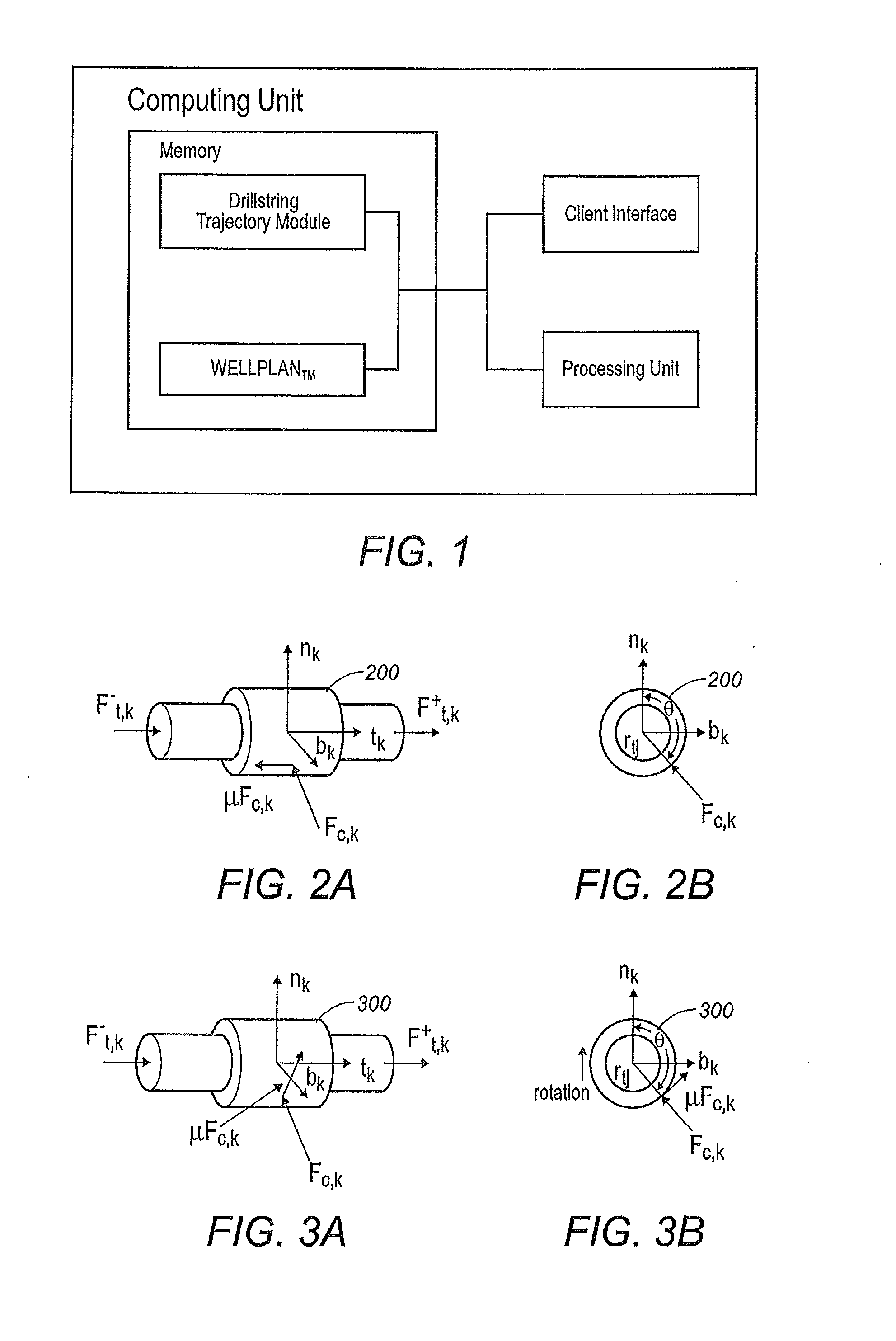
[0020]The present invention may be implemented through a computer-executable program of ins...


PUM


Abstract

Systems and methods for modeling drillstring trajectories by calculating forces in the drillstring using a traditional torque-drag model and comparing the results with the results of the same forces calculated in the drillstring using a block tri-diagonal matrix, which determines whether the new drillstring trajectory is acceptable and represents mechanical equilibrium of drillstring forces and moments.

Description

CROSS-REFERENCE TO RELATED APPLICATIONS[0001]The priority of PCT Patent Application No. PCT / US09 / 50211, filed on Jul. 10, 2009, is hereby claimed, and the specification thereof is incorporated herein by reference.STATEMENT REGARDING FEDERALLY SPONSORED RESEARCH[0002]Not applicable.FIELD OF THE INVENTION[0003]The present invention generally relates to modeling drillstring trajectories. More particularly, the present invention relates to calculating forces in the drillstring using a traditional torque-drag model and comparing the results with the results of the same forces calculated in the drillstring using a block tri-diagonal matrix, which determines whether the new drillstring trajectory is acceptable and represents mechanical equilibrium of drillstring forces and moments.BACKGROUND OF THE INVENTION[0004]Analysis of drillstring loads is typically done with drillstring computer models. By far the most common method for drillstring analysis is the “torque-drag” model originally desc...

Claims


Application Information

Patent Timeline
IPC IPC(8): G06F17/16
CPCE21B17/00
Inventor MITCHELL, ROBERT FRANKLIN
Owner LANDMARK GRAPHICS
Why Eureka
Try Eureka