Image sensor

Active Publication Date: 2012-05-17
ARNOLD & RICHTER CINE TECHN & BETRIEBS
View PDF3 Cites 12 Cited by
  • Summary
  • Abstract
  • Description
  • Claims
  • Application Information

AI Technical Summary

Benefits of technology

[0010]It is the underlying object of the invention to provide an image sensor of the initially

Problems solved by technology

A separate data output is also not usually provided for each column line and/or each column amplifier with a plurality of data outputs since a substantial space requirements and thus cost expense is associated with every data output.
As a rule, the individual data outputs cannot be manufactured completely identically with one another.
There is a problem with s

Method used


Image

  • Image sensor
  • Image sensor
  • Image sensor

Examples


Embodiment Construction

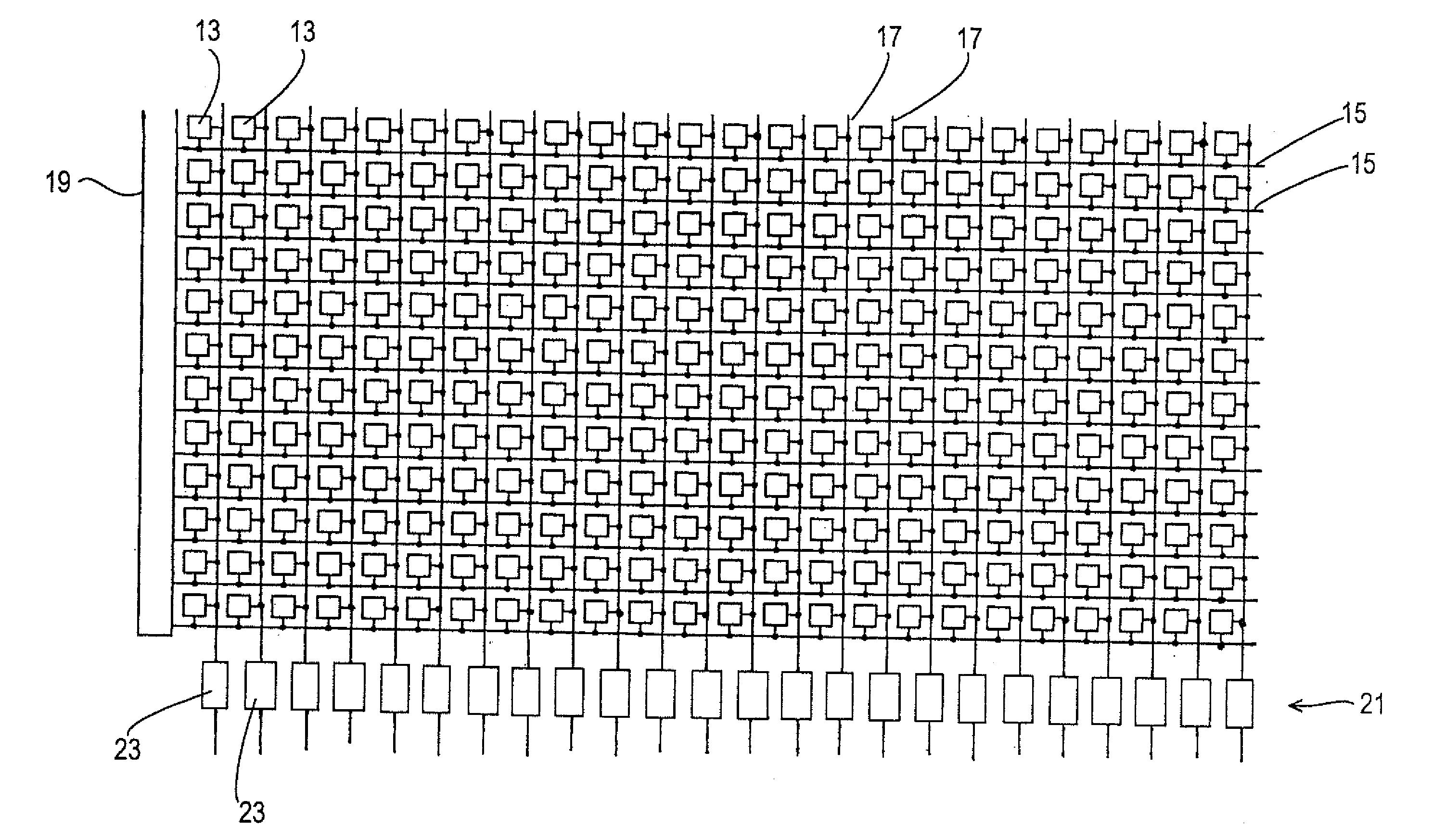
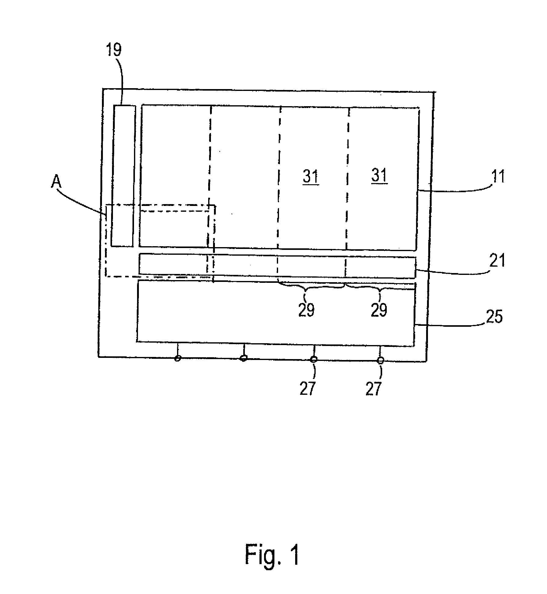
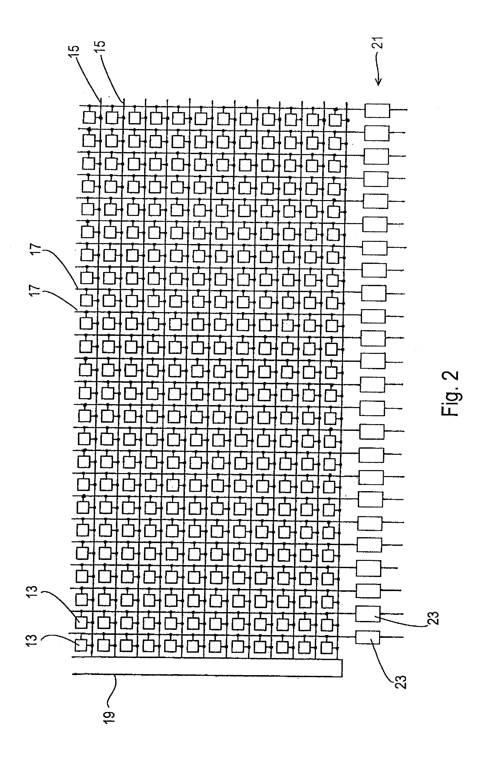
[0043]The single-channel image sensor shown in FIGS. 1 and 2 includes an image field 11 which is formed from a plurality of pixels 13 which are arranged along rows and columns. A separate row selection line 15 is provided for each row; a separate column line 17 for each column. The reading out of the image sensor takes place row-wise. For this purpose, the pixels 13 of the respective row are switched to the column lines 17 on the basis of control signals which are transmitted by means of the respective row selection line 15. A row addressing logic 19 is provided for addressing the row selection line 15 associated with the respective row to be read out. Differing from the simplified representation in accordance with FIG. 2, a plurality of column lines 17 can also be provided for each column, with each column line 17 of a column only being able to be associated with some of the pixels 13 of this column.

[0044]A row 21 of column amplifiers 23 is provided beneath the image field 11. The ...


PUM


Abstract

An image sensor for electronic cameras includes a plurality of light sensitive pixels arranged in rows and columns, wherein the pixels of a respective column can be read out via a respective column line and includes a plurality of data outputs, wherein a plurality of column lines are associated with the respective data output via at least one multiplexer device. The column lines are divided into a plurality of column line groups, wherein the respective column line group includes a plurality of column lines arranged next to one another; and wherein the number of column lines of the respective column line group corresponds to the number of the column lines associated with the respective data output.

Description

CROSS-REFERENCE TO RELATED APPLICATIONS[0001]This application claims priority of German Patent Application DE 10 2010 051 440.3 filed Nov. 15, 2010.FIELD OF THE INVENTION[0002]The present invention relates to an image sensor, in particular to a CMOS image sensor, for electronic cameras, having a plurality of light-sensitive pixels arranged in rows and columns, wherein the pixels of a respective column can be read out via a respective column line.BACKGROUND OF THE INVENTION[0003]In electronic cameras, the light-sensitive elements or pixels convert light incident through an objective of the camera into electric signals. Each of the pixels is addressed to read out an image, with each pixel corresponding to a respective picture element of the image. The pixels arranged in rows and columns form an image field of the image sensor. A signal which is proportional to a charge of the pixel collected by an exposure is conducted to an output of the image sensor.[0004]Image sensors are in partic...

Claims


Application Information

Patent Timeline
IPC IPC(8): H01L27/146
CPCH04N5/3653H04N5/378H04N5/374H04N25/677H04N25/75H04N25/76H04N25/672
Inventor CIESLINSKI, MICHAEL
Owner ARNOLD & RICHTER CINE TECHN & BETRIEBS
Why Eureka
Try Eureka