
Air-operated valve

a technology of air-operated valves and valve seats, which is applied in the direction of diaphragm valves, operating means/releasing devices of valves, engine diaphragms, etc., can solve the problems of reducing the reproducibility of the effect of the buffer member at the time of operation, shedding material from the valve part or the seat, and affecting the operation of the valve. , to achieve the effect of suppressing the sudden operation of the drive mechanism and reducing the amoun

Active Publication Date: 2012-05-17
ADVANCE DENKI KOUGYOU
View PDF6 Cites 14 Cited by
  • Summary
  • Abstract
  • Description
  • Claims
  • Application Information

AI Technical Summary

Benefits of technology

[0012]The present invention was made in consideration of the above-mentioned point and has as its object the provision of an air-operated valve which can keep the impact at the time a valve part sits on a seat from causing material of the valve part or seat from shedding and accompanying particles from contaminating a controlled fluid and thereby can maintain a high cleanliness of the controlled fluid.
[0020]According to the air-operated valve according to the aspect of the invention of claim 2, there is provided the aspect of the invention of claim 1 wherein the first piston and the second piston have a buffer member interposed between them so the impact when the first piston and the second piston contact is eased. At the same time, at the time of descent of the second piston, the impact which is applied to the valve part of the valve mechanism which is connected to the first piston is also eased.
[0022]According to the air-operated valve according to the aspect of the invention of claim 4, there is provided the aspect of the invention of claim 1 wherein the valve part has a pressure receiving part which receives a fluid pressure of the controlled fluid in an advancing direction of the valve mechanism, so a downward force is generated opposite to the upward force which is generated in the valve mechanism. Therefore, through the fluid pressure of the controlled fluid, it becomes easier to make the valve mechanism act downward.
[0024]According to the air-operated valve according to the aspect of the invention of claim 6, there is provided the aspect of the invention of claim 1 wherein a piston space between the air port and the housing body is provided with a venturi of the working air, so it is possible to reduce the amount of inflow and amount of outflow of the working air and possible to suppress sudden operations of the drive mechanism accompanying changes in the amount of working air.

Problems solved by technology

However, the biasing force of the spring with the large spring force is used to make the valve part sit on the seat, so the impact when the valve part sits on the seat is liable to cause shedding of material from the valve part or the seat.
Further, along with use of the buffer member, the buffer member probably will suffer from permanent set.
Therefore, the reproducibility of the effect of the buffer member at the time of operation can easily become degraded.
Due to this, the possibility of material being shed due to the impact when the valve part sits on the seat remains.

Method used


Image

  • Air-operated valve
  • Air-operated valve
  • Air-operated valve

Examples


Embodiment Construction

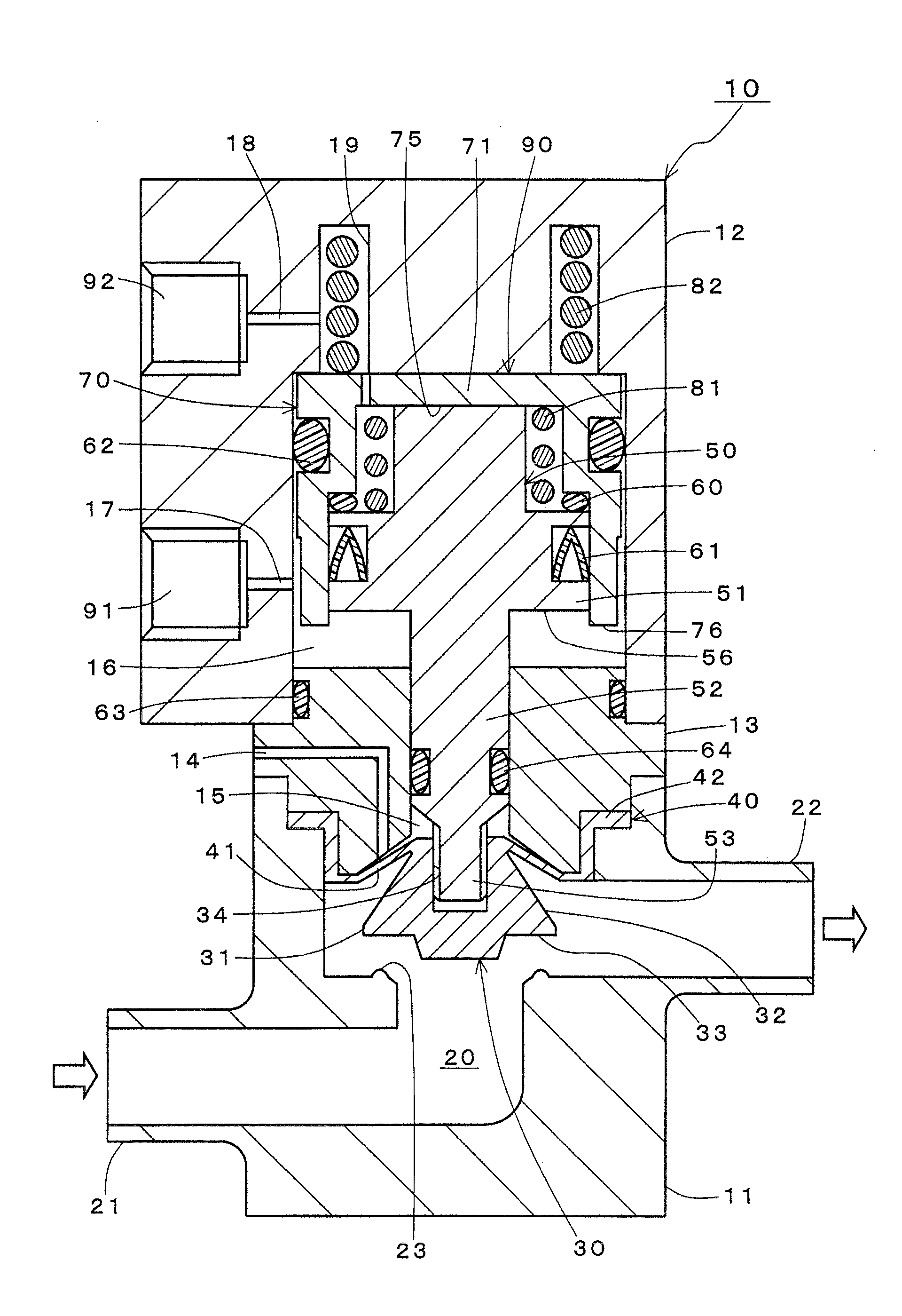
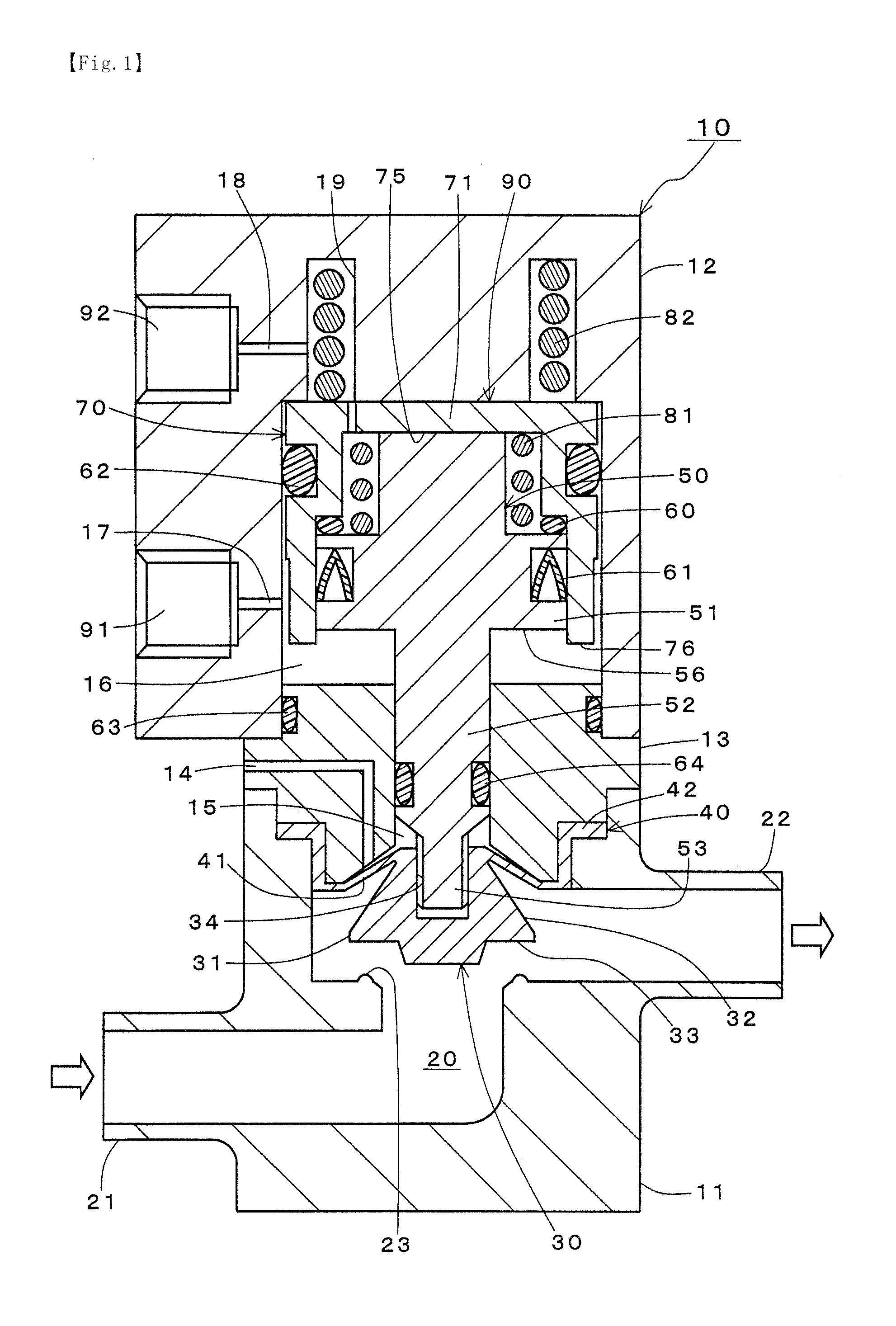
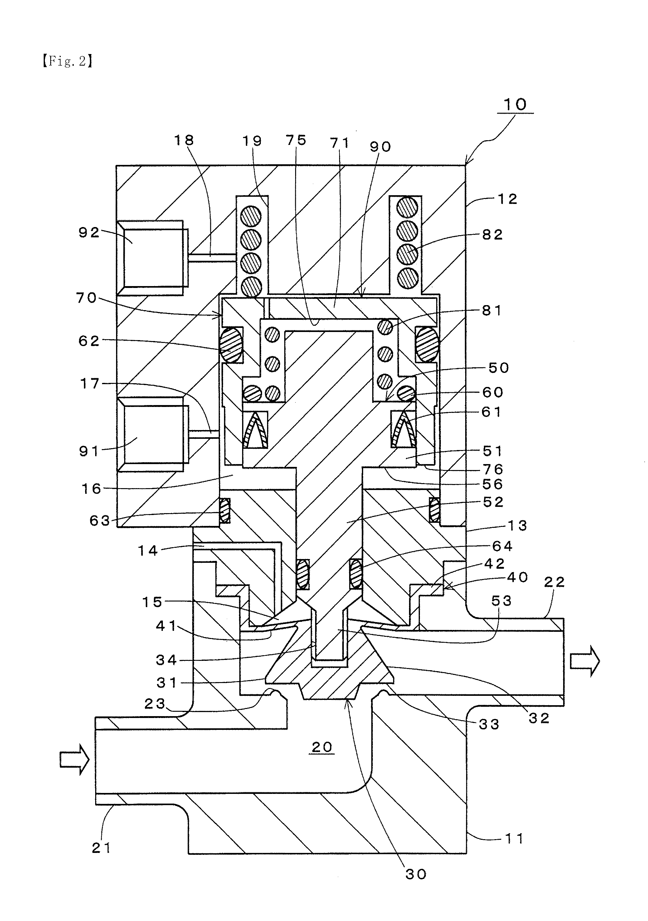
[0035]The air-operated valve 10 illustrated in the figures as the present invention is mainly installed in fluid pipelines in semiconductor production plants, semiconductor production apparatuses, etc. The air-operated valve 10 is an operating valve which controls the flow of pure water or a chemical or other controlled fluid which flows through a fluid pipeline and stops or resumes the circulation of the controlled fluid in accordance with the feed control of the working air. Note that the disclosed air-operated valve 10, as illustrated, is installed to circulate the controlled fluid from the left side of the paper (reference numeral 21) to the right side (reference numeral 22). As opposed to this, it may also be installed to circulate the controlled fluid from the right side of the paper to the left side (not shown). The method of connection of the air-operated valve 10 can be suitably changed by the design of the pipeline at the location of installation.

[0036]First, the overall c...


PUM


Abstract

An air-operated valve which can keep the impact at the time a valve part sits on a seat from causing material from shedding and thereby generating particles which contaminate a controlled fluid and thereby can maintain a high cleanliness of the controlled fluid, that is, an air-operated valve which is provided with a valve chamber body which has a valve chamber which forms a seat, a valve mechanism which is provided with a valve part which seals the seat and with a diaphragm in the valve chamber, and a housing body which houses a drive mechanism which uses working air to make the valve mechanism advance and retract to drive and control it to open and close the seat, the drive mechanism provided with a first piston, a first spring which biases the first piston, a second piston which is slidably housed in the housing body and slidably houses the first piston inside it and which pushes the first piston, and a second spring which biases the second piston, the spring force of the second spring being made larger than the spring force of the first spring.

Description

BACKGROUND OF THE INVENTION[0001]1. Field of the Invention[0002]The present invention relates to an air-operated valve, more particularly relates to an air-operated valve which suppresses the generation of particles caused when a valve part is seated on a seat.[0003]2. Description of the Related Art[0004]In the production of semiconductors etc., the pure water for washing the silicon wafers and the chemicals and other fluids for etching are required to be extremely high in cleanliness. Specifically, in the road map for next generation semiconductors, which foresees larger scale integration of semiconductors and greater miniaturization of processing, reduction of the line width in circuit patterns to 20 nm or less is being targeted. Therefore, intermixture of particles of 20 nm or larger size in the fluid would have a major impact on the product yield. From this, the members which circulate the fluid while maintaining its cleanliness have great significance.[0005]For example, a conve...

Claims


Application Information

Patent Timeline
Patent Type & Authority Applications(United States)
IPC IPC(8): F16K1/00
CPCF16K31/1225F16K7/17F15B15/22F16K31/143F16K31/145F16K47/08
Inventor SAKAI, TAKAHIROMATSUZAWA, HIRONORIIZUMO, SHUJISASAO, KIMIHITO
Owner ADVANCE DENKI KOUGYOU
Learn More