Support component structure

a technology of supporting components and components, which is applied in the mounting of support structures, electrical apparatus casings/cabinets/drawers, servers, etc., can solve the problems of easy accidental drop of mainboards by operators, difficulty in ensuring the safety of the mainboard, so as to increase the weight of the goods, reduce the weight of the operator, and increase the space of mounting and dismounting

Inactive Publication Date: 2012-05-17
INVENTEC CORP
View PDF2 Cites 14 Cited by
  • Summary
  • Abstract
  • Description
  • Claims
  • Application Information

AI Technical Summary

Benefits of technology

[0009]Accordingly, the present invention is a support component structure, so that when a mainboard is mounted or dismounted, an operator is assisted by the support component structure, so as to solve a problem in which a printed circuit board is easy to be accidentally dropped during a mounting or dismounting process because when the printed circuit board is mounted or dismounted, the mounting and dismounting space around an electronic device is insufficient, and it is difficult for the operator to find a point to employ a force on.
[0010]The present invention provides a support component structure, which comprises a tray and at least one auxiliary support element. The tray is mounted on a frame of an electronic device in a combination manner, and is used to load a printed circuit board, so as to make it easy for the operator to push the printed circuit board into the frame, and to dismount the printed circuit board in the frame to take out. The auxiliary support element is mounted on the tray, and presses against the frame, so as to increase the weight of the goods able to be born by the tray.
[0011]According to the support component structure of the present invention, a pressing force direction of the auxiliary support element parallels a direction of the mounting and dismounting of the printed circuit board, so as to resist a force moment generated by the tray during the mounting or dismounting of the printed circuit board.
[0012]The effect of the support component structure of the present invention is as follows. The bearding board is added so as to provide a support platform, and thus the space of the mounting and dismounting is increased on one hand, and on the other hand the weight held by an operator is reduced when the operator puts the printed circuit board on the tray, so that the mounting and dismounting process becomes easier and the printed circuit board is not easily dropped on the ground.
[0013]In addition, the auxiliary support element pressing against the frame is added to increase the loading capacity of the tray, so that the tray is not out of shape due to overloading when the printed circuit board is put on the tray.

Problems solved by technology

In order to make the computing capability of the server stronger, an operator is required to mount a plurality of mainboards in the case, and therefore the mounting and dismounting of the mainboards in the limited space becomes a time-consuming and laborious job.
Since it is not easy to employ a force due to small space, when the mainboards are mounted in the case, it is easy for the operator to accidentally drop the mainboards.
Moreover, in order to enable the server to have the strong computing capability, a plurality of Central Process Units (CPUs) and display cards are mounted on the mainboards, so that each of mainboards is somewhat heavy, and the heaviness easily incurs occupational injuries to the operator in the long run.
Since the price of each of the mainboards is not low, if the mainboard is accidentally dropped during the mounting and the dismounting, unnecessary station erection cost is incurred.

Method used


Image

  • Support component structure
  • Support component structure
  • Support component structure

Examples


first embodiment

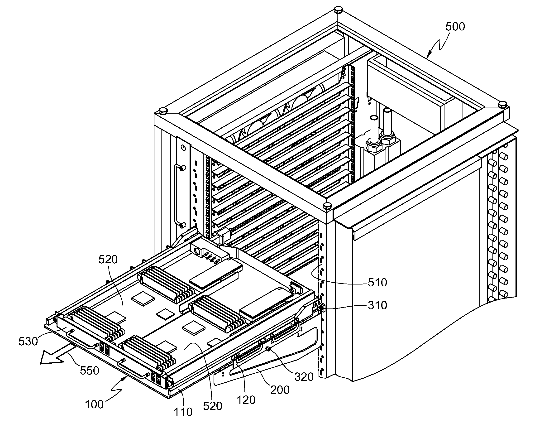
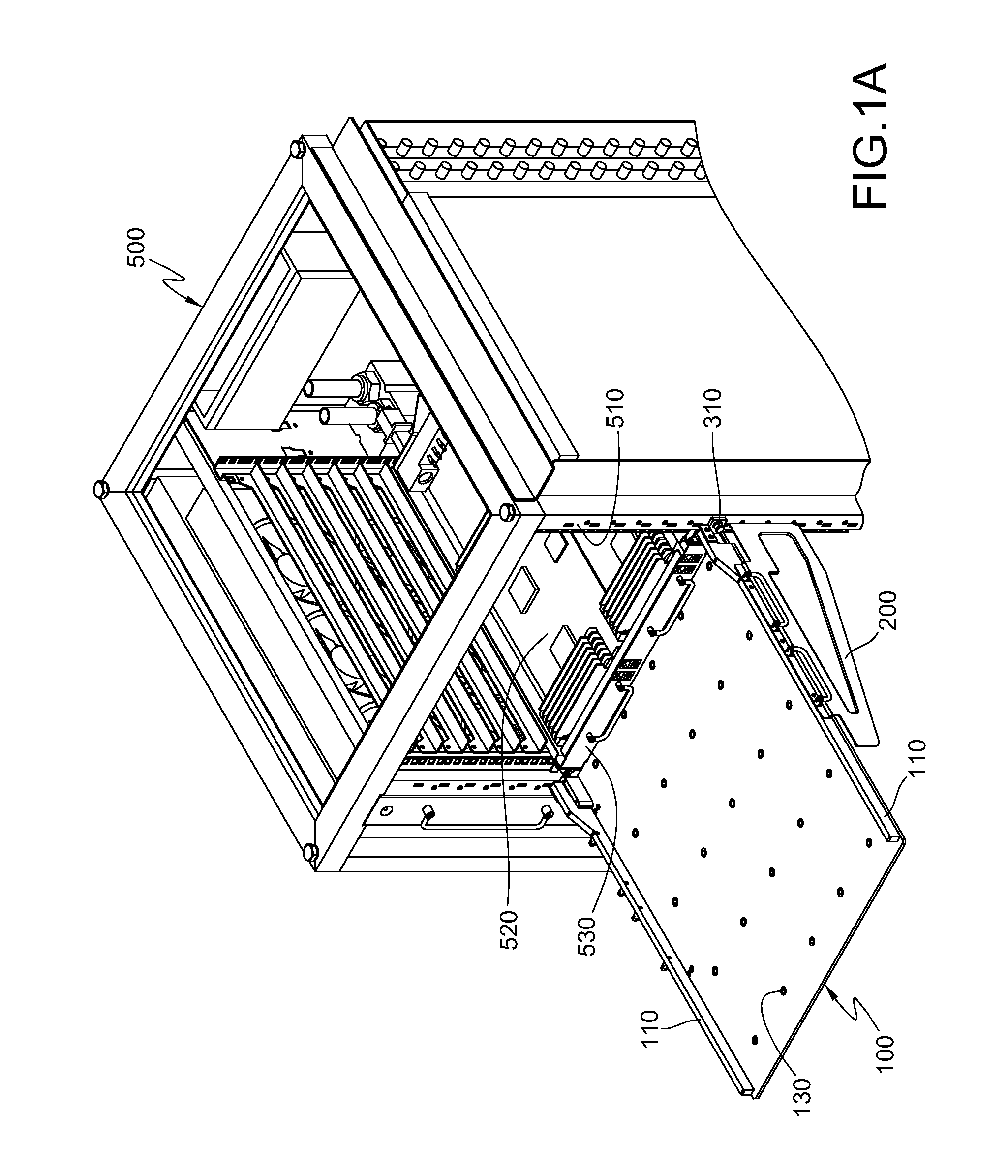
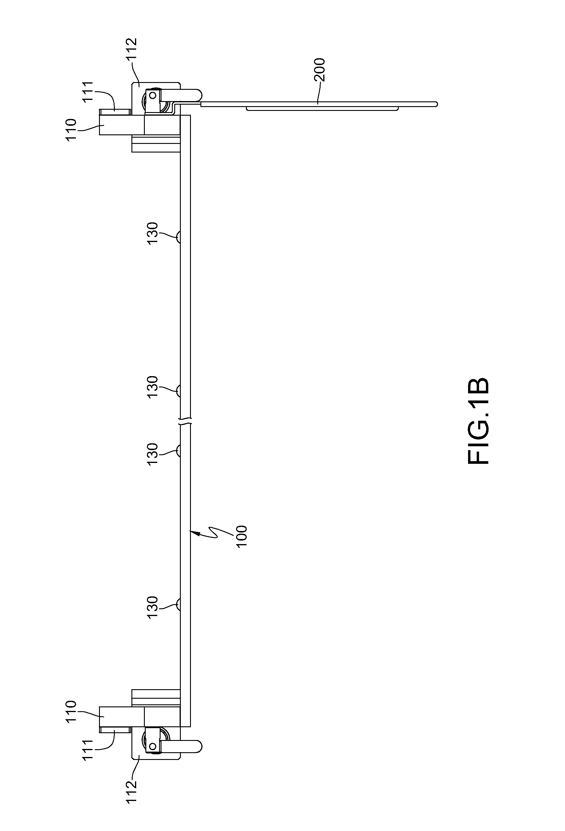
[0029]Referring to FIG. 1A and FIG. 1B, the support component structure according to the present invention comprises a tray 100 and an auxiliary support element 200. When it is required to mount or dismount the printed circuit board 520, the tray 100 is first mounted on a frame 510 of an electronic device 500 in a combination manner, so that the printed circuit board 520 can be pushed into or taken out from the frame 510, and when the mounting or dismounting of the printed circuit board 520 ends, the tray 100 is dismounted from the frame 510.

[0030]The auxiliary support element 200 is disposed on any side of two opposite sides of the tray 100, so as to improve the bearing capacity of a single side of the tray 100.

[0031]In addition, the combination manner of the present invention refers to that the tray 100 is combined to the frame 510 through a clasp structure. When various printed circuit boards 520 are mounted, an erection location of the tray 100 is adjusted according to a locatio...

third embodiment

[0034]Referring to FIG. 3A to FIG. 4, a support component structure according to the present invention comprises a tray 100 and at least one auxiliary support element 200. When it is required to mount or dismount a printed circuit board 520, a tray 100 is first mounted on a frame 510 of an electronic device 500 in a combination manner, so that the printed circuit board 520 can be pushed into or taken out from the frame 510, and when the mounting or dismounting of the printed circuit board 520 ends, the tray 100 is dismounted from the frame 510.

[0035]The auxiliary support element 200 is mounted on the tray 100, and presses against the frame 510. The pressing, by the auxiliary support 200, against the frame 510 generates a pressing force, so that the auxiliary support element 200 employs a support force on the tray 100, and thus an upper limit of the bearing the tray 100 is increased.

[0036]A rolling ball 130 is embedded in the tray 100, and a part thereof protrudes from a bearing surf...


PUM


Abstract

A support component structure is removably installed on an electronic device, and is used to mount or dismount a printed circuit board in a frame of the electronic device. The support component structure includes a tray and at least one auxiliary support element. The tray is mounted on the frame in a combination manner, and is used to load the printed circuit board, so that the printed circuit board is mounted or dismounted in the frame. The auxiliary support element is mounted on the tray, and presses against the frame, so as to increase the weight that can be born by the tray.

Description

CROSS-REFERENCE TO RELATED APPLICATIONS[0001]This non-provisional application claims priority under 35 U.S.C. §119(a) on Patent Application No. 099222301 filed in Taiwan, R.O.C. on Nov. 17, 2010, the entire contents of which are hereby incorporated by reference.BACKGROUND OF THE INVENTION[0002]1. Field of Invention[0003]The present invention relates to a support component structure, and more particularly to a support component structure erected on an electronic device, which is used to assist in mounting or dismounting of a printed circuit board in a frame.[0004]2. Related Art[0005]Nowadays, demand for computer equipment, such as desktop computers, notebook computers, and servers, is increasingly greater, and in order to obtain the latest and powerful function, consumer usually upgrades computer configurations.[0006]In recent years, a network world is formed gradually, and people's life is inseparable from the network (such as internet surfing, online games, or the Bulletin Board Sy...

Claims


Application Information

Patent Timeline
Patent Type & Authority Applications(United States)
IPC IPC(8): H05K7/16
CPCH05K7/1485H05K5/0204H05K7/1494
Inventor NI, CHUNG-SHENGYANG, CHUN-YING
Owner INVENTEC CORP
Why Eureka
Try Eureka