Surgical tool

a surgical tool and tool body technology, applied in the field of medical devices, can solve the problems of inability to examine the region of interest in real time, minimally invasive procedures,

Active Publication Date: 2012-05-17
DUNE MEDICAL DEVICES
View PDF5 Cites 47 Cited by
  • Summary
  • Abstract
  • Description
  • Claims
  • Application Information

AI Technical Summary

Problems solved by technology

It is very often the case that such minimally invasive procedures are incapable of examining the region of interest (e.g. the type of the tissue thereon) in real time just prior to removing the tissue portion.

Method used


Image

  • Surgical tool
  • Surgical tool
  • Surgical tool

Examples


Embodiment Construction

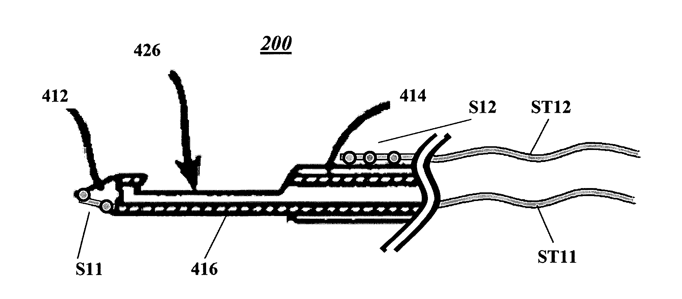
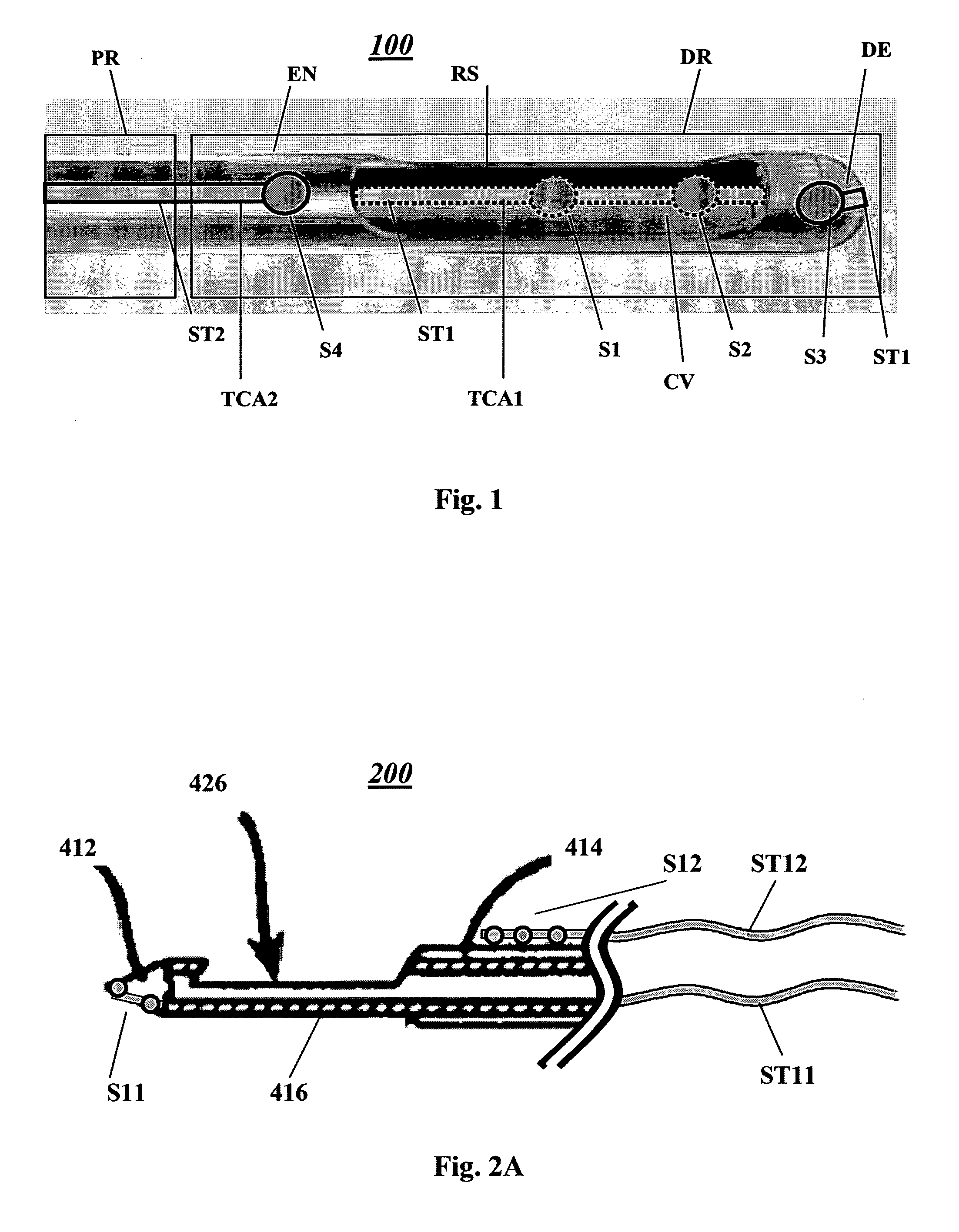
[0035]Reference is made to FIG. 1 illustrating schematically a surgical tool 100 according to an embodiment of the present invention configured an operable for tissue removal and collection procedure / operation. The surgical tool has proximal and distal regions, PR and DR, respectively, and defines a cavity CV for collection of a removed tissue sample. The surgical tool 100 includes a tissue removal assembly and a tissue characterization assembly. The latter includes at least one sensor (four sensors in the present example S1, S2, S3 and S4) arranged at the distal region DR of the surgical tool 100 and connected to at least one impedance controlled signal transmission structure of the surgical tool 100 extending in between the proximal region PR and the distal region DR and further within the distal region DR towards the locations of the sensors thereon. Accordingly, impedance controlled signal transmission structure provides controlled impedance signal transmission in between the pr...


PUM


Abstract

A surgical tool for use in a tissue removal procedure from a subject is described. The surgical tool has proximal and distal regions and at least one sensor for sensing one or more predetermined conditions located at a distal region of the surgical tool. And a substantially flat signal transmission structure electrically connected with the at least one sensor and extending between the location at the distal region and the proximal region. The signal transmission structure is configured for providing impedance controlled signal transmission between the at least one sensor and the proximal region.

Description

FIELD OF THE INVENTION[0001]This invention is generally in the field of medical devices, and relates to a surgical tool, such as a biopsy tool or the like for tissue removal.BACKGROUND OF THE INVENTION[0002]Minimally invasive surgical procedures are widely used today instead of major surgery procedures, or as preliminary procedures allowing inspection of diseased / abnormal tissues of the subject (e.g. patient's body). In such procedures, relatively small surgical tools are typically directed through the body portion towards the region of interest therein (for example utilizing natural cavities (lumens) in the body, or minimal surgical openings, e.g. single-aperture or multi-aperture laparoscopy).[0003]It is very often the case that such minimally invasive procedures are incapable of examining the region of interest (e.g. the type of the tissue thereon) in real time just prior to removing the tissue portion. Various techniques have been developed to facilitate tissue inspection while ...

Claims


Application Information

Patent Timeline
Patent Type & Authority Applications(United States)
IPC IPC(8): A61B10/00
CPCA61B10/0266A61B10/06A61B10/0275A61B5/05A61B5/0538A61B2505/05A61B2562/227
Inventor HASHIMSHONY, DANCOHEN, GIL
Owner DUNE MEDICAL DEVICES
Why Eureka
Try Eureka