Surgical implant

a surgical and implant technology, applied in the field of surgical implants, to achieve the effect of convenient surgical procedure and convenient handling

Active Publication Date: 2017-10-24
JOHNSON & JOHNSON MEDICAL GMBH
View PDF14 Cites 0 Cited by
  • Summary
  • Abstract
  • Description
  • Claims
  • Application Information

AI Technical Summary

Benefits of technology

[0012]The object of the invention is to provide a surgical implant, in particular useful for hernia repair, which can be easily handled and which facilitates the surgical procedure.

Problems solved by technology

A polygonally shaped implant has a generally well-defined and compact form, which assists the surgeon in estimating the boundaries of the implant, which often is not straightforward because part of the implant may be hidden by bodily tissue.

Method used


Image

  • Surgical implant
  • Surgical implant
  • Surgical implant

Examples


first embodiment

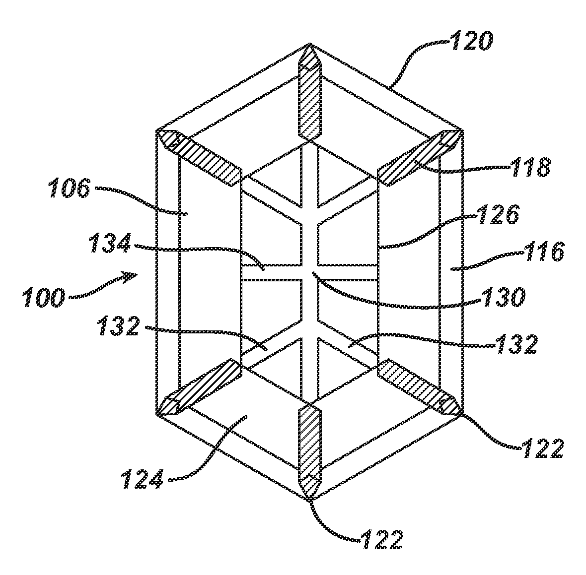
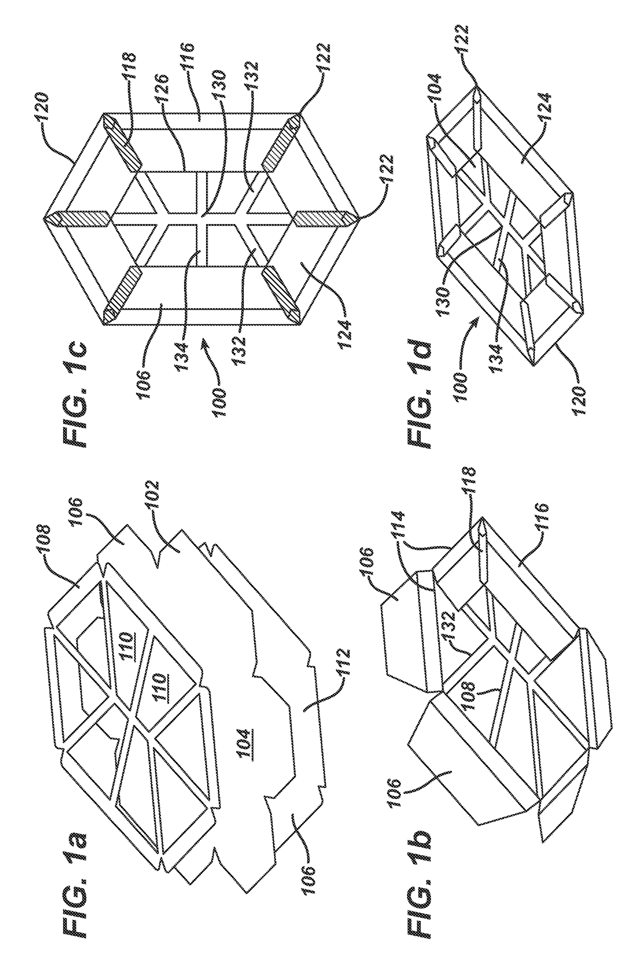
[0041]FIG. 1 illustrates a surgical implant, which is designated by reference numeral 100, as well as a process of manufacturing the implant 100.

[0042]As shown in the explosion view of FIG. 1(a), the implant 100 is made of three parts. One part is a blank 102 consisting of a mesh-like material, in the embodiment a knitted, undyed monofilament polypropylene mesh (PROLENE™ Polypropylene Mesh of Ethicon; non-absorbable) comprising a filament thickness of 89 μm. The blank 102 defines a basic structure 104 of the implant 100 plus six flaps 106.

[0043]On top of the blank 102, FIG. 1(a) shows a marking layer 108 composed of a dyed (violet) film of poly-p-dioxanone (PDS) having a thickness of 50 μm (absorbable) and comprising a total of eight openings 110. The openings 110 can be punched or cut, e.g. by laser-cutting.

[0044]The third part visible in FIG. 1(a) is the blank of an anti-adhesive film 112. In the embodiment, the anti-adhesive film 112 is a MONOCRYL film (undyed) of 20 μm thickness...

second embodiment

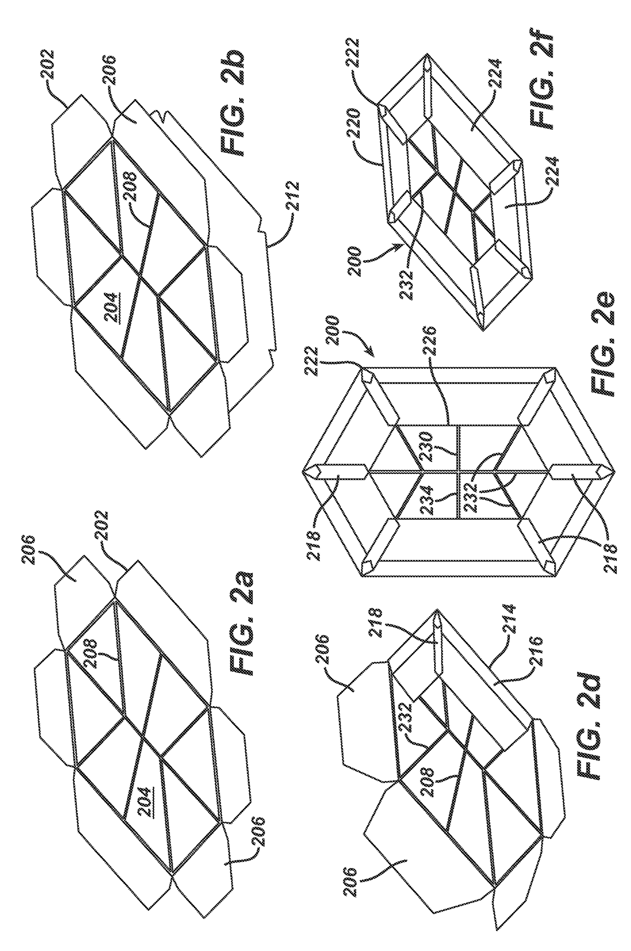
[0054]the surgical implant, designated by reference numeral 200, is illustrated in FIG. 2. The implant 200 is similar to implant 100. For that reason, the parts and components of the implant 200 are not explained again in detail. In the following, only the differences between the implants 100 and 200 are pointed out. In FIG. 2, the respective associated reference numerals from FIG. 1 have been increased by 100.

[0055]Blank 202 is cut from a knitted partially absorbable mesh material made from undyed monofilaments of polypropylene (89 μm thick; PROLENE Polypropylene) and dyed (violet) monofilaments of poly-p-dioxanone (81 μm thick; PDS).

[0056]In implant 200, a center marking 230 and directional indicators 232 are not provided via a film-like marking layer, but by threads 208 of absorbable violet poly-p-dioxanone monofilaments (109 μm thick; PDS), which are sewn to blank 202 in order to form the center marking 230, six directional indicators 232, a middle line indicator 234 as well as ...

third embodiment

[0058]the surgical implant, designated by reference numeral 300, is illustrated in FIG. 3. The implant 300 is similar to implant 200. Again, the respective associated reference numerals have been increased by 100. In implant 300, the material for blank 302 and sewn marking threads 308, respectively, is the same as in implant 200.

[0059]In contrast to implant 200, anti-adhesive film 312 (again of undyed MONOCRYL film) is only 10 μm thick and is connected across its entire surface to blank 302. To achieve the latter, during the lamination process the heat is controlled to sufficiently soften or melt the PDS filaments in the blank 302 opposing the anti-adhesive film 312 and not just in the marking threads 308. In the overlap areas 318, the folded flaps 306 are fused by ultrasonic welding in a strip-like shape, as in the other embodiments.

[0060]FIG. 3(a) shows the blank 302 with the marking threads 308, FIG. 3(b) additionally the anti-adhesive film 312, FIG. 3(c) the partially finished i...


PUM


Abstract

A surgical implant (100) comprises a mesh-like, flexible basic structure (104) having a center area and an outer periphery (120), wherein the outer periphery (120) has a polygonal shape with N corners (122), N being at least 3. The implant (100) may comprise at least two pockets (124), each pocket (124) extending from a peripheral line which connects two corners (122) of the outer periphery (120) of the basic structure (104) towards the center area of the basic structure (104). The center area of the basic structure (104) can be marked by a center marking (130), wherein directional indicators (132) point from the center marking (130) to at least two corners (122) of the outer periphery (120) of the basic structure (104).

Description

CROSS REFERENCE TO RELATED APPLICATIONS[0001]This application claims priority from German Patent Application DE 102013004486.3 filed Mar. 14, 2013 the disclosure of which is hereby incorporated by reference in its entirety.FIELD OF THE INVENTION[0002]The invention relates to a surgical implant, in particular to a surgical implant having an areal basic shape and comprising a mesh-like, flexible basic structure. The implant can be applied, e.g., as a ventral hernia device in the intraperitoneal space, but may be useful also for other indications of ventral hernia defects (like umbilical hernia defects, incisional hernia defects), for hernia prevention and for repairing a tissue or muscle wall defect in general.BACKGROUND OF THE INVENTION[0003]EP 2 032 073 A discloses an implantable medical device comprising a tissue repair material having two sides (faces) and an outer perimeter (periphery) with at least one side adapted for ingrowth of cells. A cuff is formed from the outer perimeter...

Claims


Application Information

Patent Timeline
Patent Type & Authority Patents(United States)
IPC IPC(8): A61B17/04A61F2/00
CPCA61F2/0063A61F2002/0068
Inventor HARMS, VOLKERCOOPER, SUSANKAISER, DAJANAWALTHER, CHRISTOPH
Owner JOHNSON & JOHNSON MEDICAL GMBH
Why Eureka
Try Eureka