
Powered brush

Inactive Publication Date: 2012-05-24
THE GILLETTE CO
View PDF7 Cites 37 Cited by
  • Summary
  • Abstract
  • Description
  • Claims
  • Application Information

AI Technical Summary

Benefits of technology

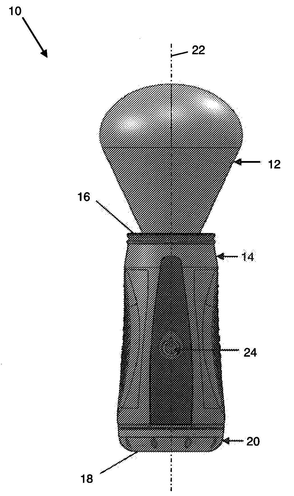
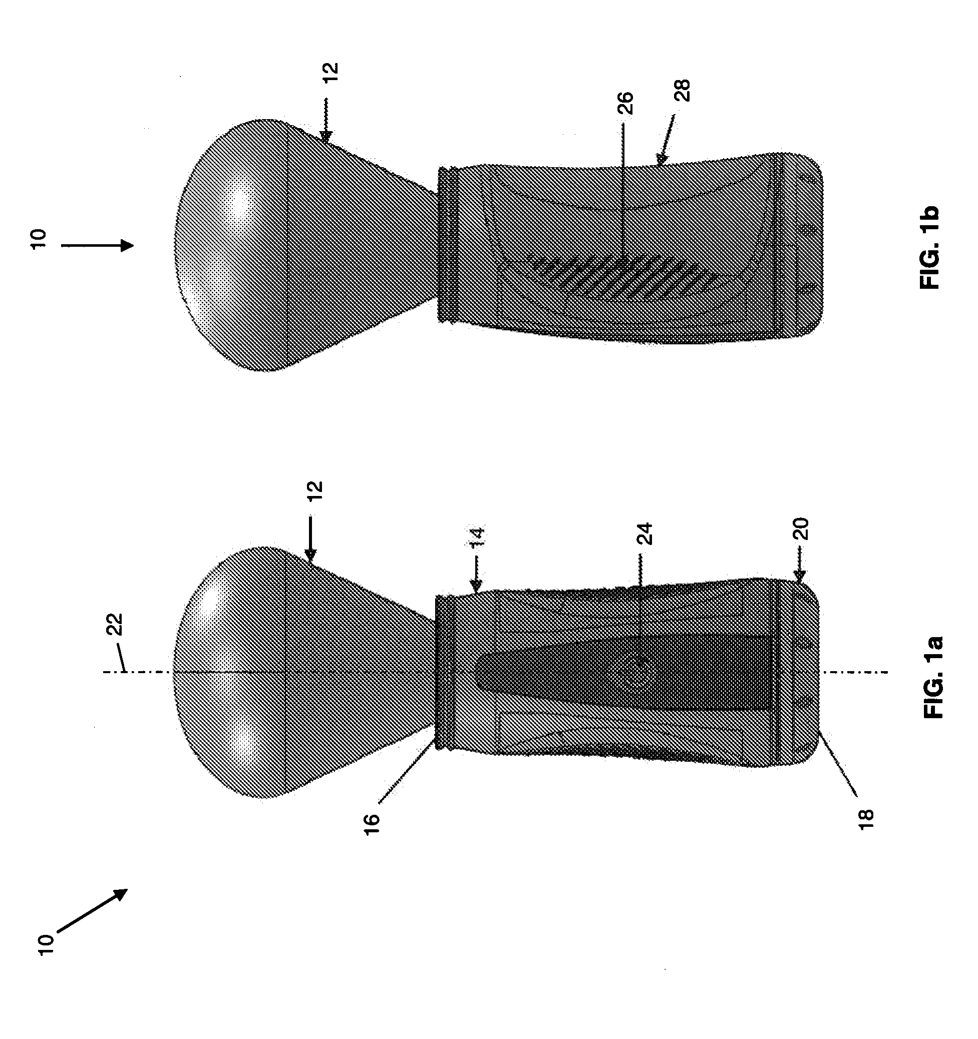
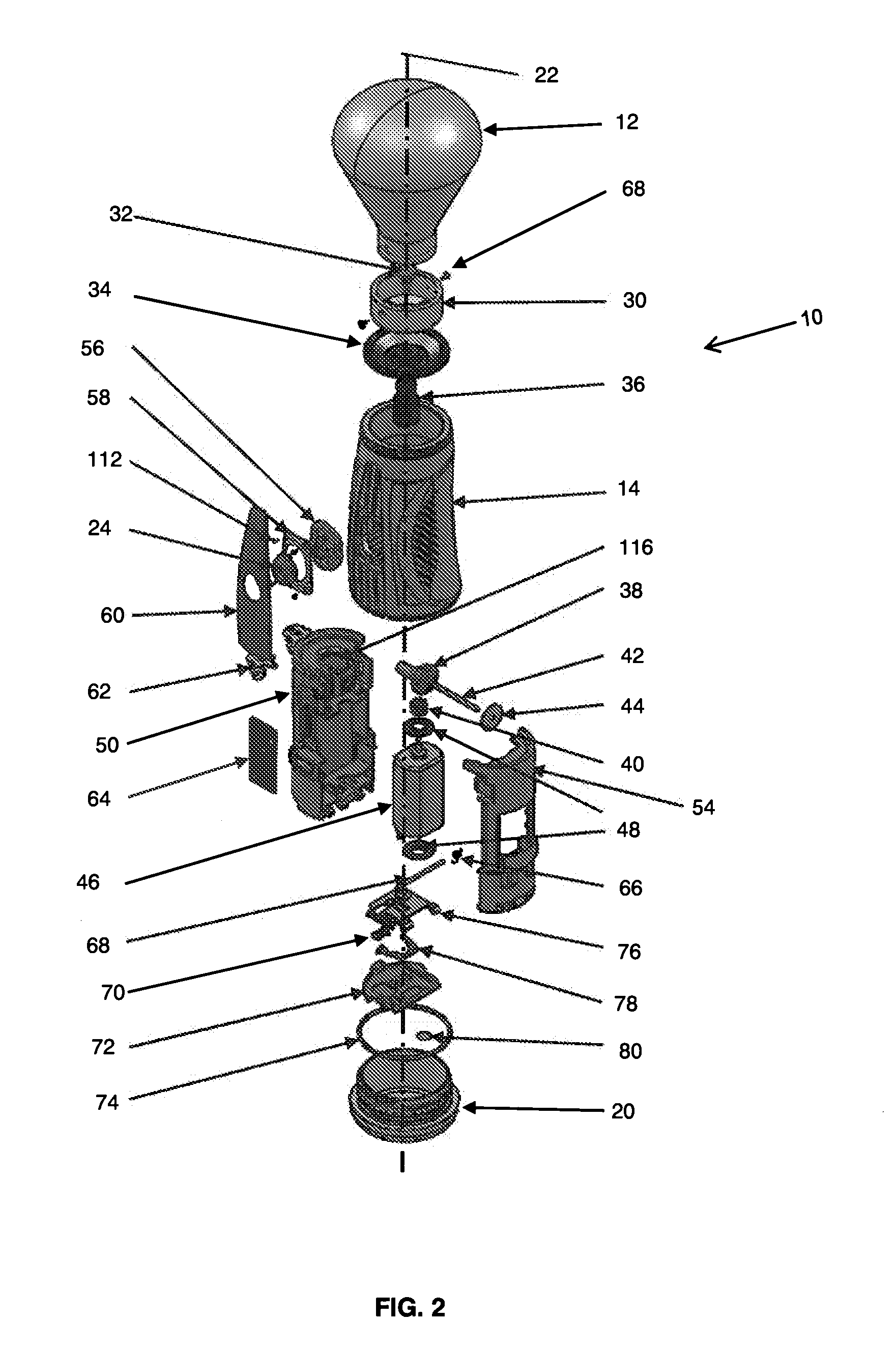
[0005]In one aspect, the invention features, in general, a powered brush providing an automated motion to plurality of bristles, thus enhancing the ability to stimulate the skin, raise hairs off the face, exfoliate, and lubricate and moisturize the skin while applying shave cream to a user's face. The powered brush comprises a handle having a top end, a bottom end and a longitudinal axis therebetween. A brush cup which is movable relative to the handle is disposed at the top end of the handle. A brush head is attached to the brush cup. The brush head comprises a plurality of bristles projecting away from the top end in a longitudinal direction. A motor comprising a drive shaft is mounted inside of the handle. The motor is joined to an internal mechanism coupling the motor drive shaft to the brush cup. The internal mechanism translates rotational movement of the motor drive shaft to reciprocating longitudinal motion of the brush cup such that in use, the brush cup and corresponding brush head attached thereto oscillate linearly in the longitudinal direction.
[0006]In one embodiment, the internal mechanism comprises a first gear attached to the motor drive shaft and a second gear meshed with the first gear. The second gear includes an elongated cam feature attached thereto. The elongated cam feature interfaces with a cam follower link connected to the brush cup. The elongated cam feature engages a cam slot in the cam follower link and allows complete rotation of the elongated cam feature as the outer surface of the elongated cam feature contacts the cam slot. As the first gear drives the second gear, the elongated cam feature rotates driving the cam follower link in a linear, up and down motion causing the brush cup and corresponding brush head attached thereto to oscillate linearly in the longitudinal direction.

Problems solved by technology

The application of lather is dependent on the motion of the user's hand which can limit the benefits of using a brush if not performed correctly.

Method used


Image

  • Powered brush
  • Powered brush
  • Powered brush

Examples


Embodiment Construction

[0030]The shaving razor according to the present invention will be described with reference to the following figures which illustrate certain embodiments. It will be apparent to those skilled in the art that these embodiments do not represent the full scope of the invention which is broadly applicable in the form of variations and equivalents as may be embraced by the claims appended hereto. Furthermore, features described or illustrated as part of one embodiment may be used with another embodiment to yield still a further embodiment. It is intended that the scope of the claims extend to all such variations and equivalents.

[0031]The powered brush 10 according to the present invention is shown in FIGS. 1a and 1b. The powered brush 10 includes a handle 14 having a top end 16 including the brush head 12 and a bottom end 18 including a battery cap 20. A longitudinal axis 22 extends between the top end 16 and the bottom end 18. Power button 24 is disposed in the side of the handle 14 bet...


PUM


Abstract

A powered brush is provided comprising a plurality of automated bristles that are driven in order to facilitate application of shave cream to a user's face while raising hairs off the face and stimulating, exfoliating, lubricating and moisturizing the skin. The powered brush comprises a handle having a top end, a bottom end and a longitudinal axis therebetween. A brush head comprises a plurality of bristles projecting away from the top end in a longitudinal direction is attached to a brush cup which is disposed at the top end of the handle and is movable relative thereto. An internal mechanism couples a motor drive shaft to the brush cup. The internal mechanism translates rotational movement of the motor drive shaft to reciprocating motion of the brush cup causing the brush cup and corresponding brush head attached thereto to oscillate linearly in the longitudinal direction.

Description

FIELD OF THE INVENTION[0001]The present invention relates to brushes and particularly to brushes used in applying shave cream and more particularly to powered shave brushes used in applying shave cream.BACKGROUND OF THE INVENTION[0002]This invention relates to a brushes typically used in applying shave cream. Traditional shaving brushes are typically formed of a barrel-shaped handle with a plurality of bristles protruding from one end of the handle. The handles are typically made of wood, metal or plastic while the bristles of lower quality brushes are made of synthetic materials, such as nylon, and the bristles of higher quality brushes are made of natural materials, such as badger hair.[0003]Shaving brushes have been used historically to prepare hair and skin ahead of wet shaving, for example with a double edged razor blade or with a wet shaving safety razor. A user would work up soap or gel into a lather either against their face, in a shaving mug / bowl, or in the palm of their we...

Claims


Application Information

Patent Timeline
IPC IPC(8): A46B13/00
CPCA46B13/02A61C17/3445A46B2200/1033
Inventor SABISCH, MARKUSPORT, HOLGERCROGGON, HUGH JAMES
Owner THE GILLETTE CO
Learn More