Utility knife

Inactive Publication Date: 2012-05-24
REIBOLD ROBERT
View PDF24 Cites 9 Cited by
  • Summary
  • Abstract
  • Description
  • Claims
  • Application Information

AI Technical Summary

Benefits of technology

[0009]This invention has potential to reduce the incidence of laceration, abrasion and similar injuries commonly sustained in the use of utility knives. Some embodiments of the invention can also provide for rapid adjustment of the length of the exposed cutting edge. In addition, some embodiments of the invention can provide for protection of the user in both of the above-mentioned oblique and perpendicular cutting modes, while providing for proper blade guidance and control of cutting depth in each mode.
[0010]The utility knife in accordance with a first aspect of the invention comprises an elongated handle having opposite sides extending along the direction of elongation, and opposite ends spaced from each other along the direction of elongation. A blade is fixed to, and protrudes from, the handle at one of the opposite ends of the handle. The handle is provided with a guard comprising a pair of laterally protruding guard members positioned adjacent the end of the handle from which the blade protrudes. The guard members protrude respectively from the opposite sides of the handle by a distance sufficient to prevent a user's hand from sliding past the end of the handle from which the blade protrudes.
[0012]The through hole can be an elongated through hole extending in a direction parallel to the blade, whereby, by loosening the fastener, the position of the work-engaging member relative to the handle can be adjusted. If the elongated through hole extends substantially parallel to the direction of elongation of the handle, by loosening the fastener, the position of the guard can be adjusted longitudinally for adjustment of the extent to which the blade is exposed beyond the work-engaging member. On the other hand, if the through hole extends in a direction transverse to the direction of elongation of the handle, by loosening the fastener, the angular relationship of the work-engaging member and the direction of elongation of the handle can be adjusted.
[0014]In still another embodiment, the work-engaging member is formed with two narrow ends, both aligned with the blade, and in which the blade extends through the slot in the work-engaging member between those narrow ends. In this embodiment, the narrow ends provide for improved visual guidance, enabling the user to follow a guide line drawn on a workpiece more accurately.

Problems solved by technology

Slipping of the hand along the knife handle in the direction of the blade due to fatigue, moisture, inattention and other factors can result in laceration by the cutting edge of the blade or abrasion by contact with the hard granules embedded in an asphalt shingle.
Other workers who use utility knives are subject to similar injuries.
Although some utility knives having retractable blades can be adjusted to set the cutting depth, a conventional knife in which the trapezoidal blade is secured against longitudinal movement by the engagement of protrusions within the handle with notches along its short base has no capability of rapid cutting depth adjustment.
There is a risk of injury when operating a conventional utility knife in each of these two modes.

Method used


Image

  • Utility knife
  • Utility knife
  • Utility knife

Examples


Embodiment Construction

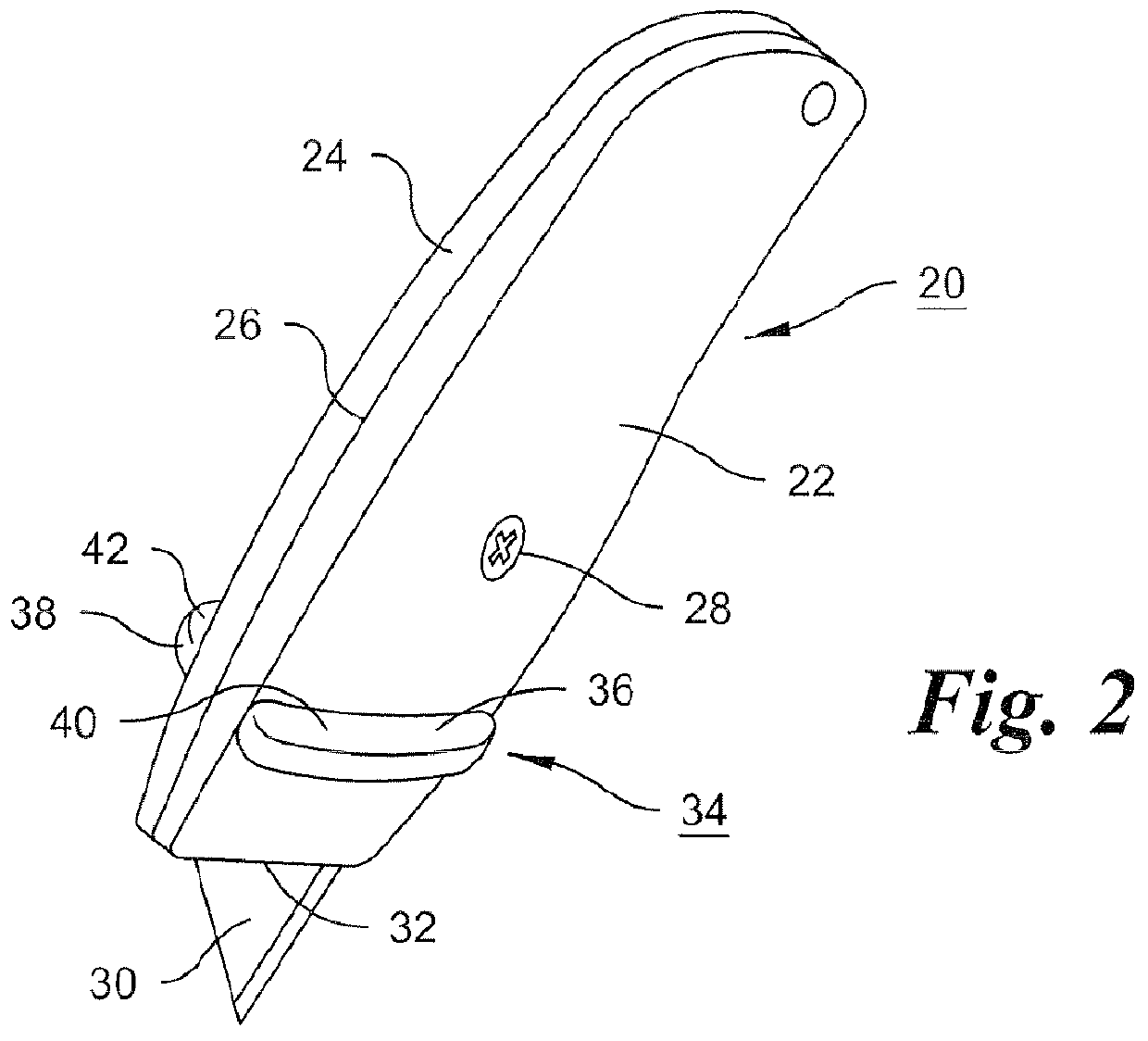
[0033]The knife 20 shown in FIGS. 1 and 2 is in most respects similar to a conventional utility knife, the knife handle being composed of two similar parts 22 and 24, which meet each other in a plane 26 with respect to which the two handle parts are substantially symmetrical. Parts 22 and 24 are secured together by a machine screw 28, which can be readily removed by means of a screwdriver, allowing the two parts to be separated from each other.

[0034]When held together by screw 28, handle parts 22 and 24 clamp a trapezoidal blade 30 in such a way that a part of the blade is exposed, protruding from a distal end 32 of the handle while the remainder of the blade is hidden inside the handle between the handle parts. As explained previously a conventional utility knife handle is typically hollow so that a space is provided for storage of spare blades, and one or both of the handle parts includes protrusions that fit into notches formed in an edge of the blade opposite form the cutting ed...


PUM


Abstract

A utility knife is provided with a guard for preventing the user's fingers from being lacerated by the blade or from being abraded by contact with material being cut. The guard can be a removable guard attachable to the knife using a fastener that also secures two halves of the knife handle together. The removable guard can include a work-engaging member with a slot through which the blade protrudes. The cutting depth, or the angle of the work-engaging member can be adjusted by providing in the guard a suitable slot through which the fastener extends. Different kinds of work-engaging members can be provided, including an insulation stripping guide, a guide having narrow ends aligned with the blade for visual guidance, and a guide having diverging sides for cutting flooring.

Description

FIELD OF THE INVENTION[0001]This invention relates to utility knives, and more particularly to a utility knife having capabilities advantageous to roofers, builders, electricians, flooring installers, and other individuals who make extensive use of such knives.BACKGROUND OF THE INVENTION[0002]A conventional utility knife comprises an elongated handle shaped to fit comfortably in an individual's hand, and a blade fixed to, and extending from one end of, the handle. A typical utility knife blade has a trapezoidal shape, with its cutting edge extending along the longer base of the trapezoid. The blade is usually replaceable, and when installed in the handle, extends therefrom in such a way that the shorter base of the trapezoid is fully or almost fully enclosed within the handle. Consequently, the exposed part of the blade is generally in the form of a trapezoid or a triangle.[0003]Ordinarily, the handle consists of two similar parts that meet each other in a plane along which the blad...

Claims


Application Information

Patent Timeline
IPC IPC(8): B26B29/02B26D7/01
CPCB26B29/02B26B1/10
Inventor REIBOLD, ROBERT
Owner REIBOLD ROBERT
Why Eureka
Try Eureka