Typically, these support systems are costly, labor intensive to install, heavy, structurally inferior, and mechanically complicated.
Placing the solar panels on the support structure can be very difficult, as can the wiring of the solar panels for array activation.
Further, some large solar panels tend to sag and flex thereby rendering the panel mounting unstable.
Another major problem with mounting large solar panel arrays is that support structures (such as those described below) are required to support the weight of the panels and hold them steady so that all the operational features can be obtained.
Unfortunately, this means that a second structural arrangement (the solar panel support) is placed on the first structural arrangement (the roof).
Very often this causes substantial stress on the original supports of the building.
Even if such additional stress or load is not severe, the stacking of two non-reinforcing structural support arrangements on each other constitutes a waste in time and material.
This installation process is often costly, inaccurate, and time-consuming.
The aforementioned ground-
mount support arrangement cannot be used as part of another structure, such as a building roof.
Notably, existing support systems require meticulous on-site
assembly of multiple parts, performed by expensive, dedicated field-labor.
Assembly is often performed in unfavorable working conditions, i.e. in harsh weather and over difficult
terrain, without the benefit of
quality control safeguards and precision tooling.
Misalignment of the overall support
assembly often occurs.
This can jeopardize the supported solar panels or other supported devices.
Further, wiring of the solar panels, once secured is also problematic.
The first is that such installations are costly.
The second is that they require substantial space, very often when such is at a premium.
Since many conventional roofs will not support a solar panel array, twice the ground space and twice the expense of a structural support arrangement is very often required to have both a building and a solar panel array.
It is difficult, however, to precisely space the panels on-site using existing support structures without advanced (and expensive) technical assistance.
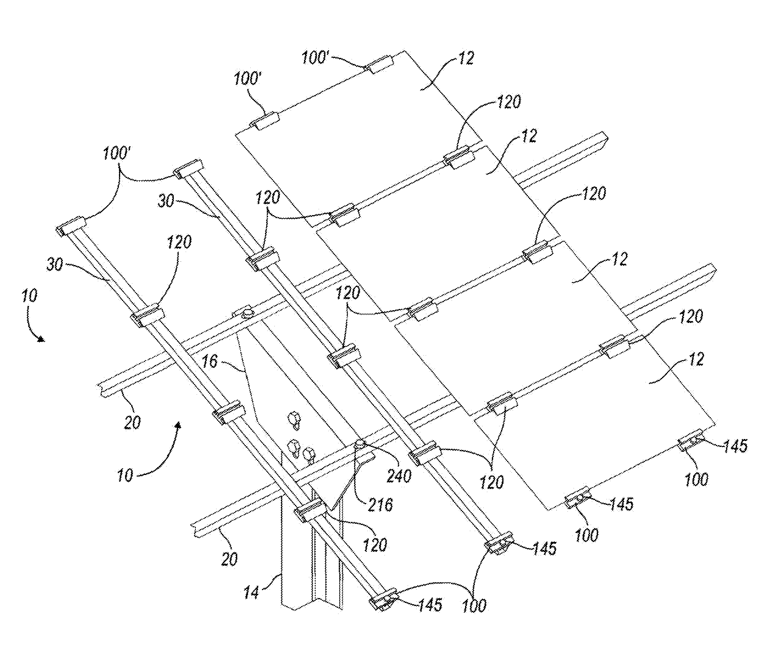
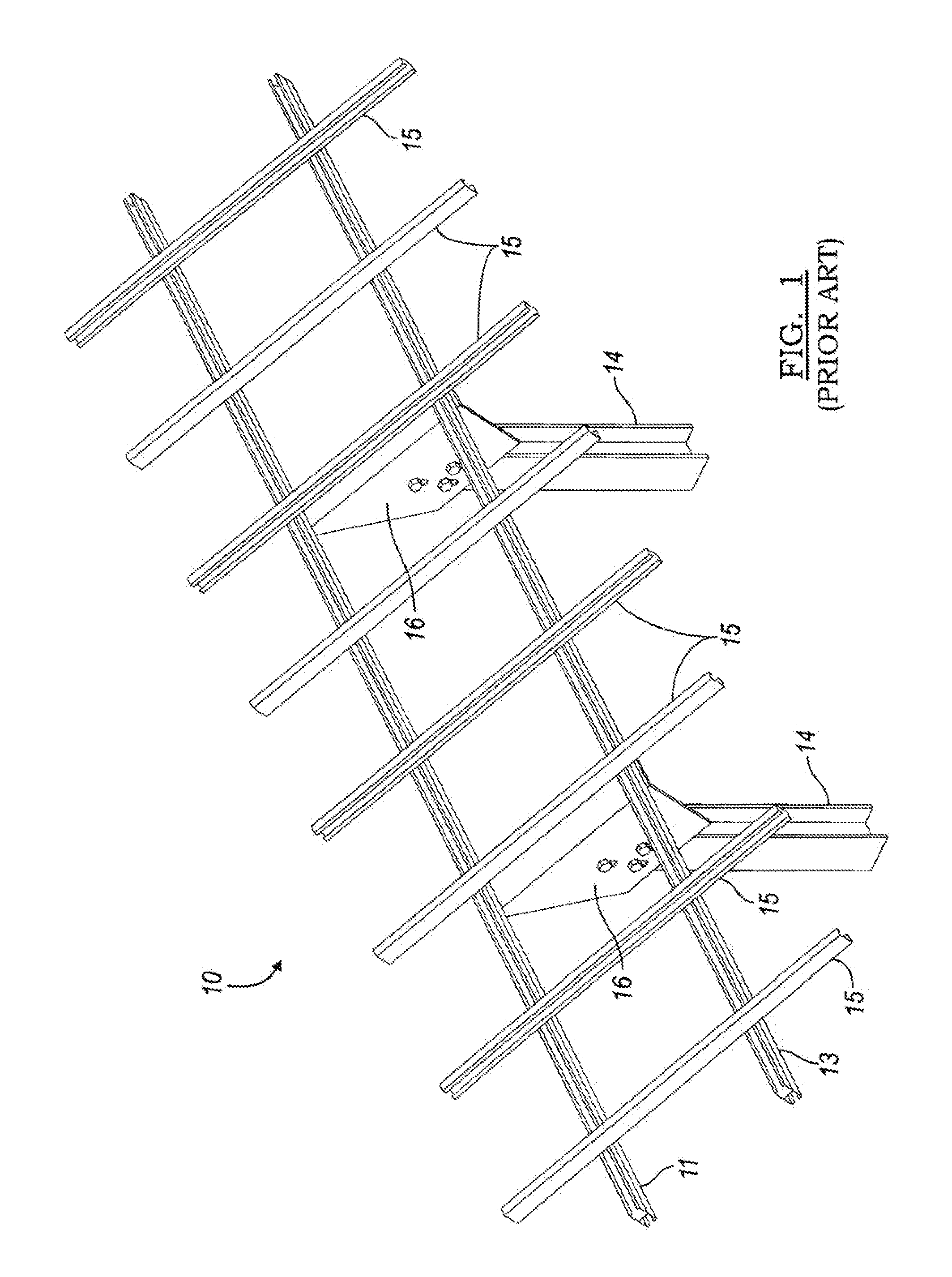
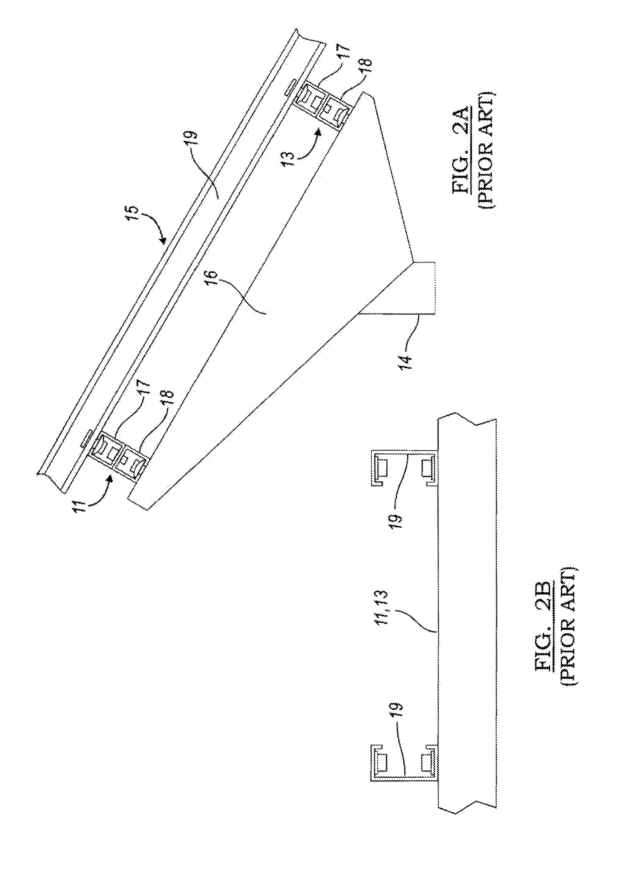
Even with a purpose-built installation to support a solar array (such as I-beams 14 and tilt mounting-bracket 16), and a two-dimensional array of support joists 11, 13 and mounting rails 15, placing individual solar panels 12 on the support structure can be problematical.
The whole process of mounting solar panels 12 using the subject clips or panel holders is extremely awkward and somewhat risky to both the panels and the installation
crew.
This is especially true if the installation
crew is not highly trained or experienced.
Unfortunately, the operation of drilling the holes on-site requires skilled workers, and even with skilled installation, might still result in misalignment of the support structure and / or the solar panels supported by that structure.
Misalignment difficulties are exacerbated by the flexing of the panels, as well as sagging permitted by the upper panel support rails.
Improper installation, which occurs frequently in conventional systems, can lead to
dislocation of the panels due to sagging or atmospheric conditions.
A wide variety of different mounting positions and array arrangements also exacerbate the stability problems caused by panel sagging or deflection.
Further, certain mounting positions will make the panels more vulnerable to atmospheric disruptions, such as those created by wind and
precipitation.
All of these variables also complicate electrical connections to the panels.
After all, this support arrangement is not always available.
However, as previously discussed, the roofs of many structures may not be capable of supporting heavy or elaborate panel support structures.
However, even a stable
flat roof presents problems for the mounting of an array of solar panels.
In particular, the panels cannot be mounted in the same manner provided using conventional art in FIGS. 1 through 4B of the present application.
Also, installation of individual panels can be an expensive and hazardous process.
Panel installation constitutes a substantial portion of installation time and thus, installation expense.
At present, none of the conventional art offers these capabilities.

