Space-saving high-density modular data pod systems and energy-efficient cooling systems

a modular data pod and modular technology, applied in the field of computing data centers, can solve the problems of high initial capital, operation and maintenance costs, power consumption capacity of the entire data center, and the traditional chiller plant spends a considerable amount of energy on the area, so as to achieve the effect of reducing the cost per kilowatt (kw) of building, deployment and operation, and facilitating resting

Active Publication Date: 2012-05-24
INERTECH IP
View PDF3 Cites 38 Cited by
  • Summary
  • Abstract
  • Description
  • Claims
  • Application Information

AI Technical Summary

Benefits of technology

[0008]The embodiments of the modular data pod systems and associated cooling systems of the present disclosure provide significant improvements and advantages over traditional data centers and their cooling systems including (1) a lower cost per kilowatt (kW) to build, deploy, and operate a data center, (2) faster deployment than stick-built construction, (3) more easily restacked and redeployed to allow the data center to keep up with new technological advances in server technology, (4) expandability, (5) compatibility with very high efficiency systems to gain the highest power use efficiency (PUE) factor, (6) space saving and efficient in their space requirements allowing for higher density capabilities (i.e., more kilowatts per square foot), (7) scalability, (8) efficiency in mechanical cooling, (9) multi-use characteristics for single deployment, large indoor warehousing, or large outdoor applications, such as data center farms, (10) energy efficiency in the containment of hot and cold aisles, (11) flexibility in their use of different types of cooling systems, and (12) capability of being modified to meet data center tier requirements for redundancy.

Problems solved by technology

There are many problems associated with the large, oversized cooling infrastructures for large data centers, including high initial capital, operation, and maintenance costs.
As a result, the traditional chiller plant spends a considerable amount of energy on areas that do not need to be cooled.
Further, one of the design constraints used to implement the traditional chiller plant is the power consumption capacity of the entire data center.
For that reason, if the data center does not run at its power consumption capacity due to load fluctuations, the efficiency of the traditional chiller plant drops significantly.
However, one of the drawbacks of the air-cooled “free cooling” system is that it operates only in a cool, dry-climate environment thereby restricting its use to limited geographical areas in the world.
However, the adiabatic-assisted system has certain cooling tolerance limitations and is incapable of providing sufficient cooling to high density data centers, e.g., data centers having IT rack loads of about 40 kW per IT rack.

Method used


Image

  • Space-saving high-density modular data pod systems and energy-efficient cooling systems
  • Space-saving high-density modular data pod systems and energy-efficient cooling systems
  • Space-saving high-density modular data pod systems and energy-efficient cooling systems

Examples


Embodiment Construction

[0044]Embodiments of the presently disclosed close-coupled cooling systems and methods will now be described in detail with reference to the drawings, in which like reference numerals designate identical or corresponding elements in each of the several views.

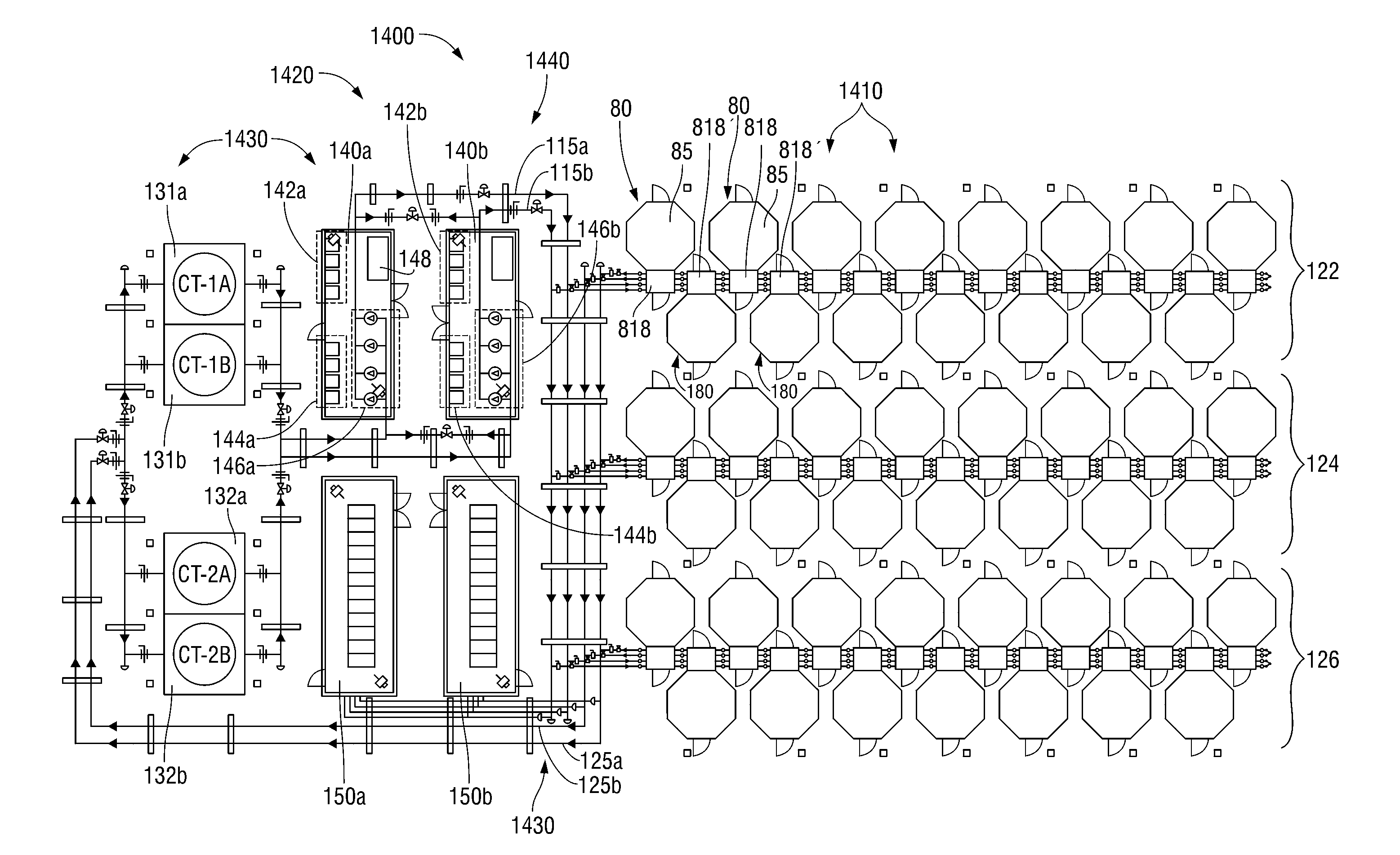
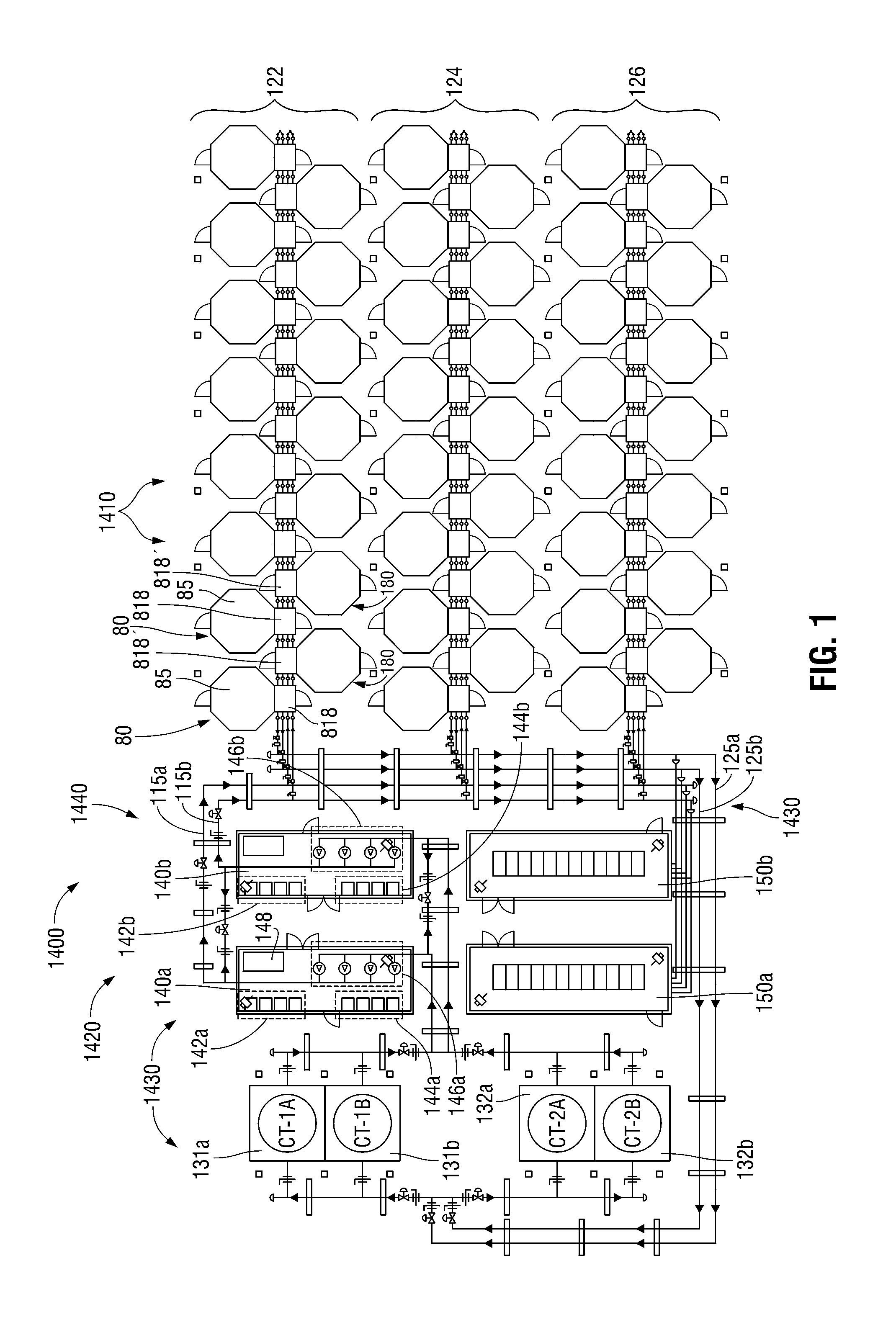
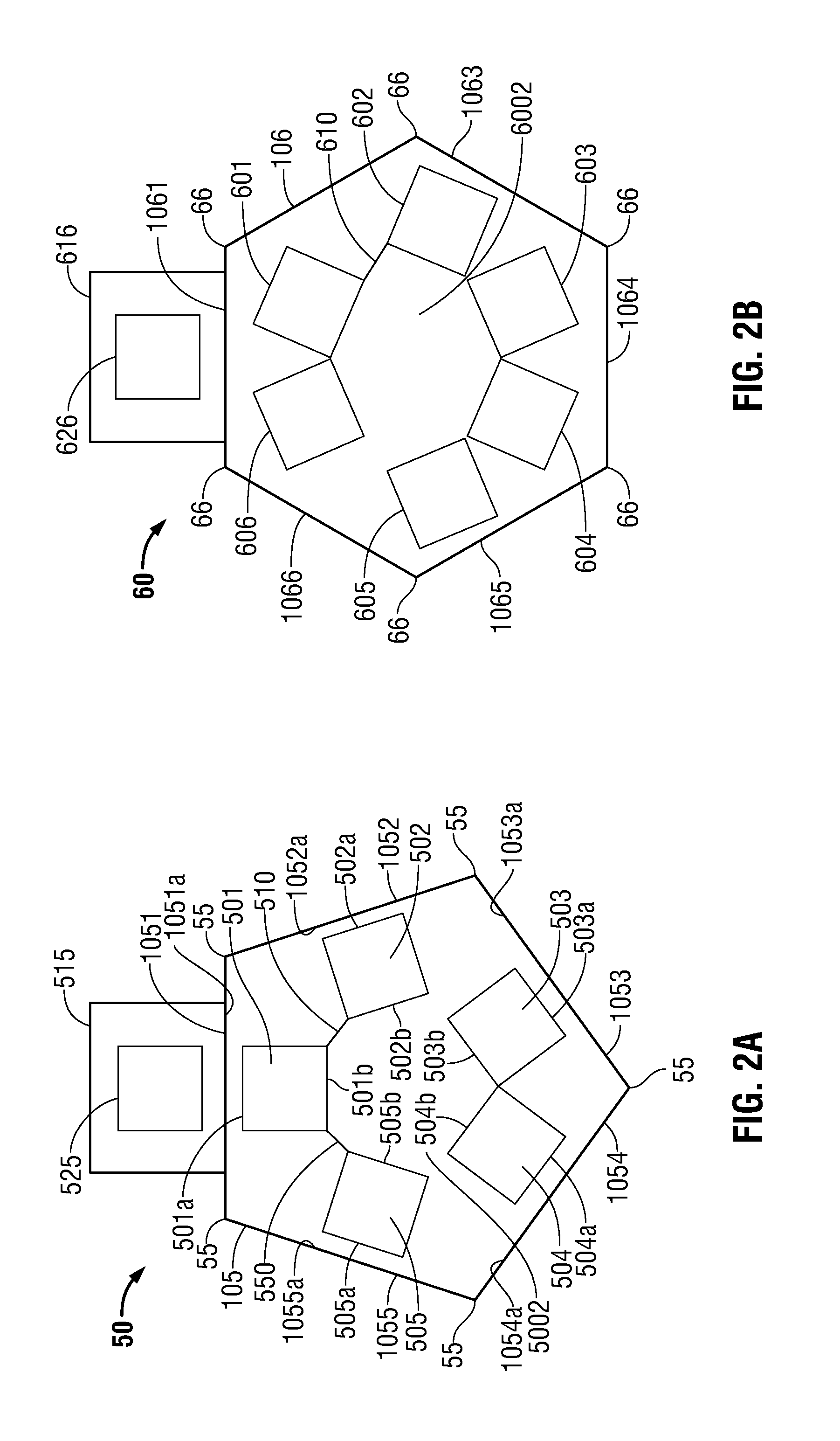
[0045]The present disclosure relates to modular data pods and related support systems for providing energy-efficient, space-saving, and high-density server rack configurations. This modular approach allows for highly efficient use of geometric shapes such as octagonal, hexagonal, and pentagonal shapes for creating a hot aisle and a cold aisle through which air circulates for cooling the server racks. These polygonal shapes allow for maximum energy-efficiency and space-savings using the benefits of both the interior and the exterior angles and sides. The interior pod shape provides a natural circular configuration for positioning server racks. As compared to the prior art, this configuration provides a more efficient way to creat...


PUM


Abstract

A space-saving, high-density modular data pod system and an energy-efficient cooling system for cooling electronic equipment and method of cooling are disclosed. The cooling system includes a free-cooling system cooling a first fluid in thermal communication with the electronic equipment using atmospheric air and a mechanical sub-cooling system coupled to the free-cooling system. The mechanical system cools a second fluid flowing in the free-cooling system as a function of an amount by which the free-cooling system has exceeded its maximum cooling capacity. The method of cooling includes using a first fluid, enabling heat transfer from the first fluid to a second fluid that has been cooled using atmospheric air, and mechanically cooling the second fluid to the extent that free cooling the first fluid is insufficient to cool the first fluid. The cooling system operates by the wet bulb temperature exceeding a first predetermined wet bulb temperature.

Description

CROSS-REFERENCE TO RELATED APPLICATIONS[0001]This application is a continuation-in-part of international application no. PCT / US2011 / 41710, which was filed on Jun. 23, 2011 and claims the benefit of, and priority to, U.S. Provisional Application Ser. No. 61 / 357,851, which was filed on Jun. 23, 2010; U.S. Provisional Application Ser. No. 61 / 414,279, which was filed on Nov. 16, 2010; U.S. Provisional Application Ser. No. 61 / 448,631, which was filed on Mar. 2, 2011; and U.S. Provisional Application Ser. No. 61 / 482,070, which was filed on May 3, 2011, the entire contents of which are hereby incorporated by reference herein.BACKGROUND[0002]1. Technical Field[0003]The present disclosure generally relates to computing data centers. More particularly, the present disclosure relates to space-saving high-density modular data pod systems and energy-efficient cooling systems for modular data pod systems.[0004]2. Background of Related Art[0005]Traditionally, large data centers rely on large, over...

Claims


Application Information

Patent Timeline
Patent Type & Authority Applications(United States)
IPC IPC(8): F25B49/02F28F27/00F25B1/00F28D15/00G05D23/00
CPCH05K7/20827H01L2924/0002H01L2924/00F25B49/00F25D17/00F28D15/00G06F1/20H01L23/34H01L23/473H05K7/20218H05K7/20763H05K7/20781H05K7/20754H05K7/20818
Inventor KEISLING, EARLCOSTAKIS, JOHNMCDONNELL, GERALD
Owner INERTECH IP
Why Eureka
Try Eureka