Muzzle velocity sensor

a technology of muzzle velocity and sensor, which is applied in the direction of measurement devices, force/torque/work measurement, measurement of explosion force, etc., can solve the problems of unreliable field measurement velocities, inability to use existing technology in field operations, and inability to accurately calculate the impact point error

Inactive Publication Date: 2012-05-24
DRS TECH CANADA
View PDF28 Cites 26 Cited by
  • Summary
  • Abstract
  • Description
  • Claims
  • Application Information

AI Technical Summary

Benefits of technology

[0007]Embodiments of the present technology are directed to systems and methods for accurately calculating a projectile muzzle velocity.

Problems solved by technology

Errors in the projectile muzzle velocity can have a significant impact on the error in the calculated impact point.
While muzzle velocities may be measured in a controlled environment, such as a laboratory or a controlled range, these measured velocities may be unreliable in the field, where conditions are continually changing.
However, the existing technology is impractical to use in field operations, requiring bulky and cumbersome equipment, changes to the projectile itself, and / or changes to the barrel of the firearm.
However, such devices are impractical for field operations because they require the marksman to fire through a large device placed in front of the firearm, preventing the marksman from remaining hidden.
However, this requires modification to the projectile itself, possibly changing certain projectile manufacturer specifications given.
However, the technology requires a magnet to be placed on the projectile body.

Method used


Image

  • Muzzle velocity sensor
  • Muzzle velocity sensor
  • Muzzle velocity sensor

Examples


Embodiment Construction

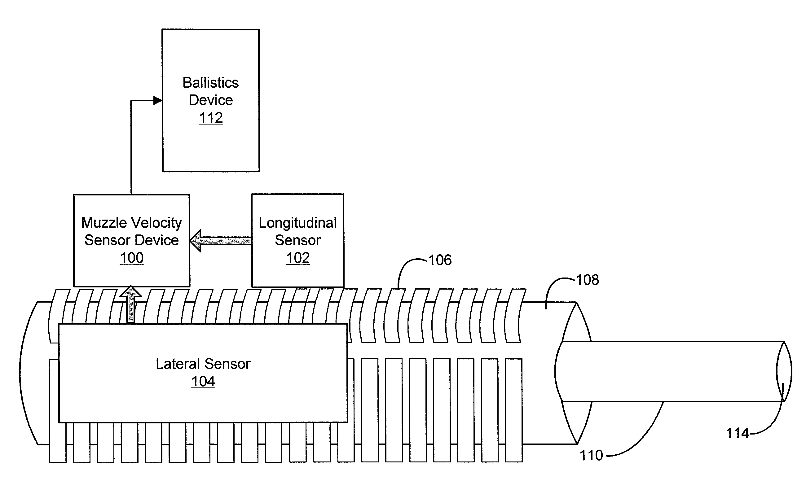
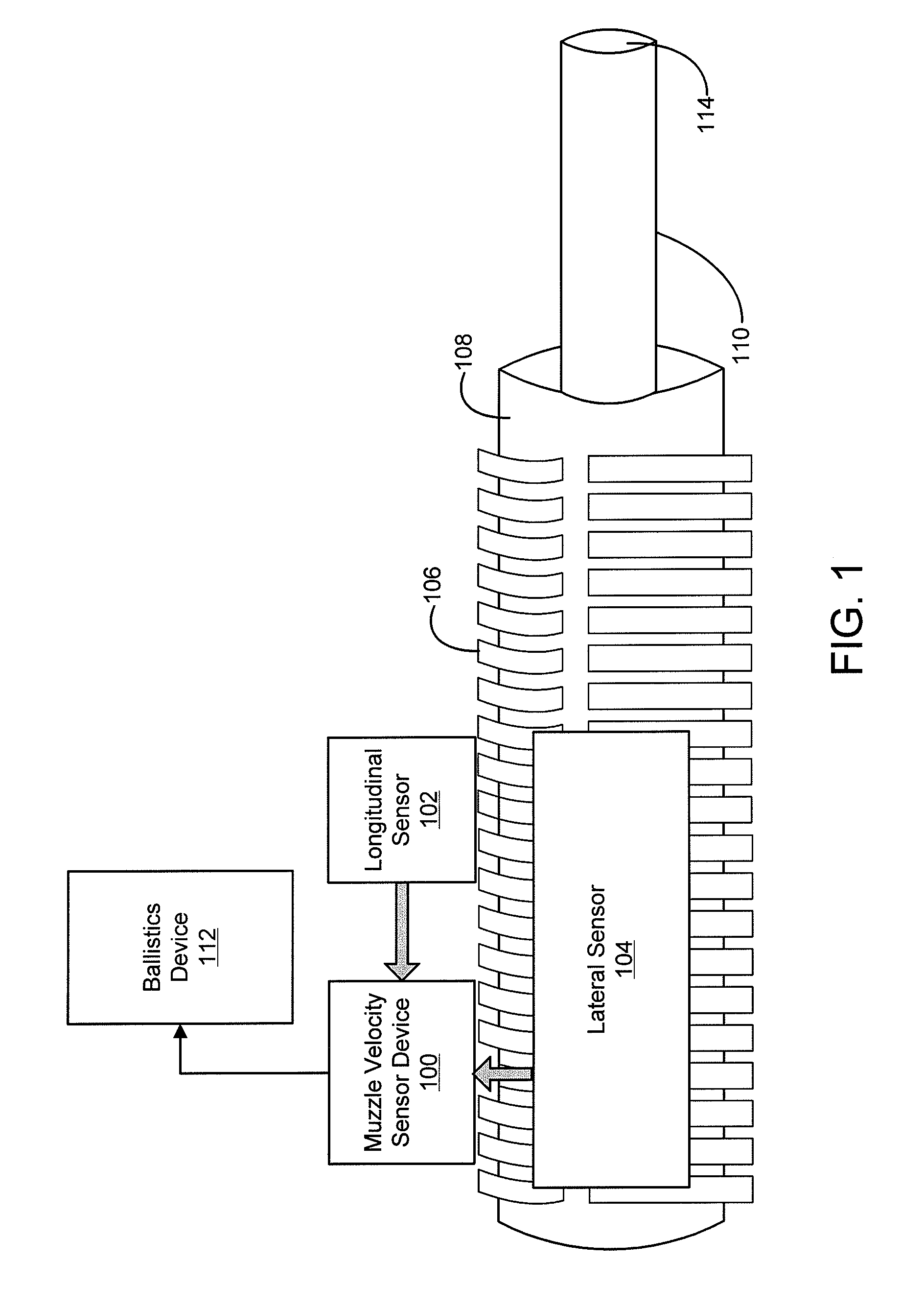
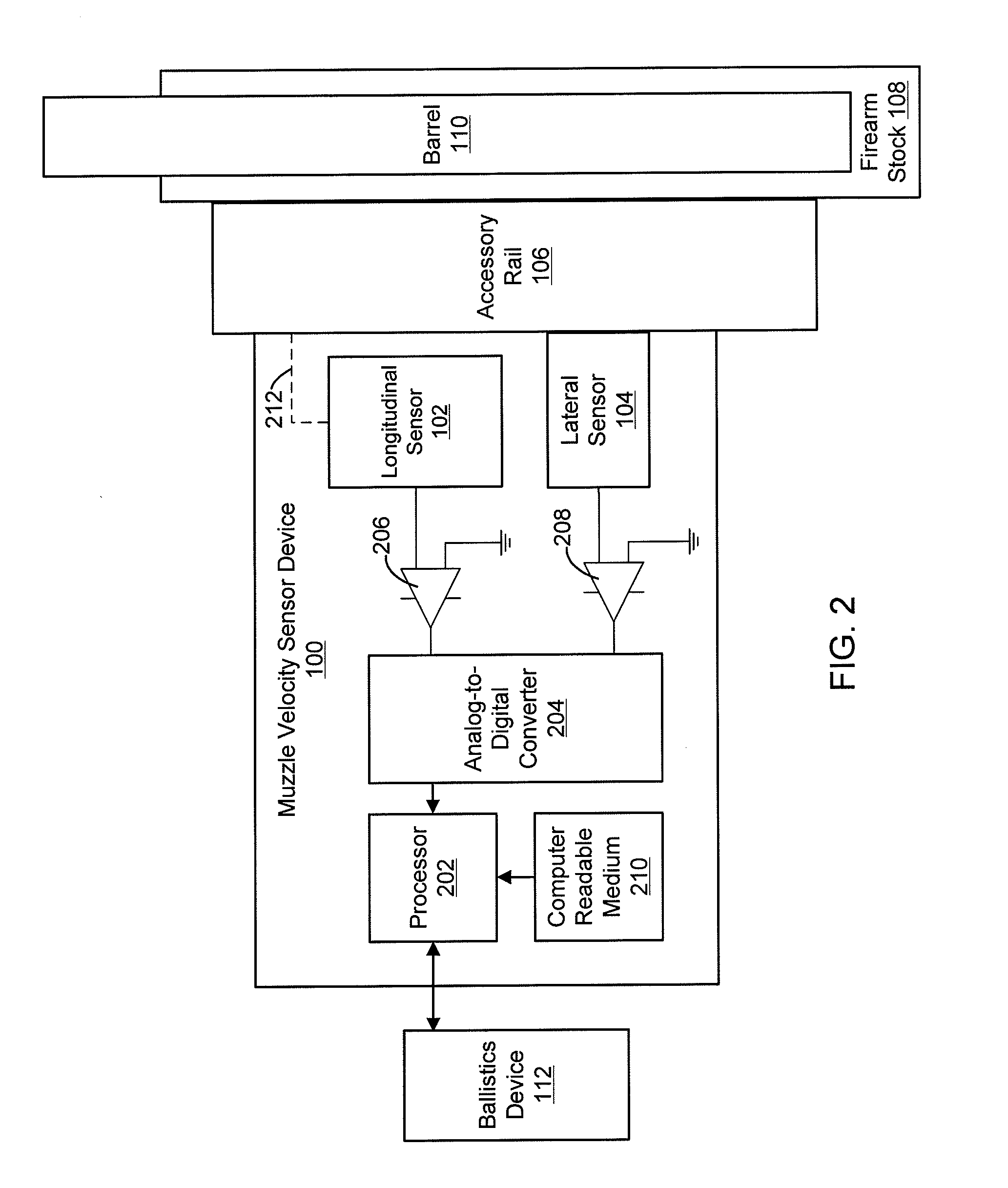
[0019]Embodiments of the technology of a muzzle velocity sensor involve the use of piezoelectric sensors placed on the exterior of a firearm. While existing technology requires modification to the firearm or to the projectile in order to measure projectile muzzle velocity, the present technology measures projectile and barrel performance for use in field operations utilizing the existing accessory rail of the firearm. The present technology does not require any modification to either the firearm or the projectile and does not require any bulky equipment that is not operationally field-deployable. The muzzle velocity sensor assists the marksman in obtaining a higher probability of hit per round by characterizing the performance of both the firearm and the projectile and by measuring the projectile muzzle velocity in the field. The muzzle velocity sensor may be applied to small arms, mortar, artillery and mobile gun platforms. The technology is scalable and may be applicable to any si...


PUM

PropertyMeasurementUnit
radiusaaaaaaaaaa
muzzle velocityaaaaaaaaaa
velocityaaaaaaaaaa

Abstract

Embodiments of the present technology are directed to systems and methods for measuring projectile muzzle velocity. A muzzle velocity sensor measures an acceleration as well as a set of events occurring within the barrel of the firearm upon a shot being fired. Using the measured data, a muzzle velocity is calculated. The muzzle velocity sensor is used externally to the firearm, requiring no changes to the firearm or the projectile.

Description

CROSS REFERENCES TO RELATED APPLICATIONS[0001]This patent application claims priority to U.S. Provisional Application No. 61 / 416,262 filed Nov. 22, 2010 entitled “Small Arms Muzzle Velocity Sensor,” which is hereby incorporated by reference in its entirety for all purposes.BACKGROUND[0002]The need to accurately hit a target on the first shot has become increasingly important for marksmen in the field, as a marksman may be responsible for an area of surveillance with a radius of up to 3000 meters. To achieve long range shots of upwards of 1000 meters or more, marksmen must calculate the settings that need to be dialed into a firearm scope to ensure that there is a high probability of hit on the intended target. The marksman typically uses a ballistics device to calculate the settings needed on the firearm scope for the intended impact point. The ballistics device uses a ballistics algorithm which integrates all present variables, such as range to target, slant angle, wind, temperatur...

Claims


Application Information

Patent Timeline
Patent Type & Authority Applications(United States)
IPC IPC(8): G01L5/14
CPCG01P3/665G01L5/14
Inventor DOWNING, WARREN JAMES
Owner DRS TECH CANADA
Why Eureka
Try Eureka