Track and bogie for suspended vehicles

a suspension vehicle and bogie technology, applied in the direction of rail engaging elements, transportation and packaging, roads, etc., can solve the problems of linear electric motors in general more expensive and less efficient than rotating electric motors, pollution, congestion and land use, etc., to prevent any significant slippage of the drive wheels, reduce the rolling resistance of each drive wheel, and ensure the stability of the system

Active Publication Date: 2012-05-24
SUPRAWAYS
View PDF1 Cites 21 Cited by
  • Summary
  • Abstract
  • Description
  • Claims
  • Application Information

AI Technical Summary

Benefits of technology

[0015]The present invention preferably uses rotating electric motors and ensures the most reliable friction possible by locating the running surface receiving the drive wheel facing downwards inside a mostly enclosed first track member provided with a downward facing opening. The contact force of a drive wheel of a bog...

Problems solved by technology

Public transportation with large vehicles in the form of metro, trolley and buses all have the problem with people having to wait for vehicles to arrive and then stop at all stations during the trips.
Cars offer the flexibility of a personal trip but have problems with pollution, accidents, congestion and land use.
The wheel traction based systems have problems with loss of traction in some weather conditions while the linear electric motor systems have an economic and efficiency problem, as linear electric motors are in general more expensive and less efficient than rotating electric motors.
For large vehicle systems like trains the uncertain traction can be compensated with long headways, i.e. inter-vehicle times. This is not possible for a system with small vehicles as the reduced track capacity would make the system economically infeasible.
One main problem with this type of configuration is that the running surfaces on each side of the track opening must be kept at a constant lateral distance.
T...

Method used


Image

  • Track and bogie for suspended vehicles
  • Track and bogie for suspended vehicles
  • Track and bogie for suspended vehicles

Examples


Embodiment Construction

[0030]In the following embodiments of the invention will be described more in detail with reference to the enclosed drawings.

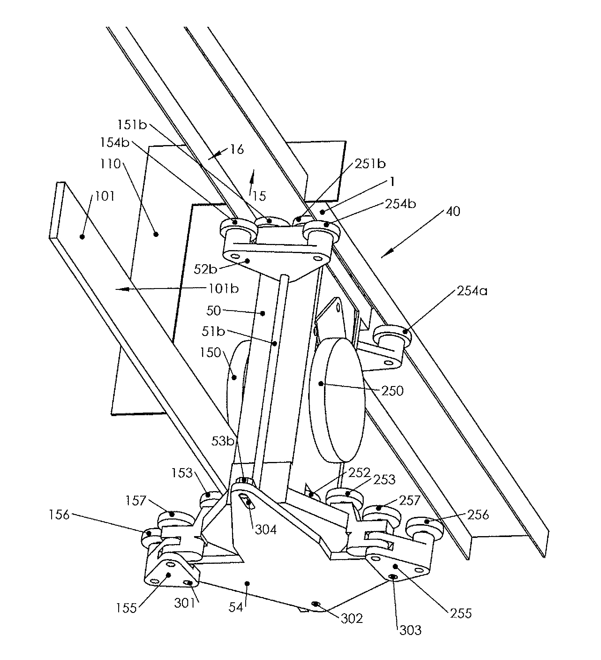
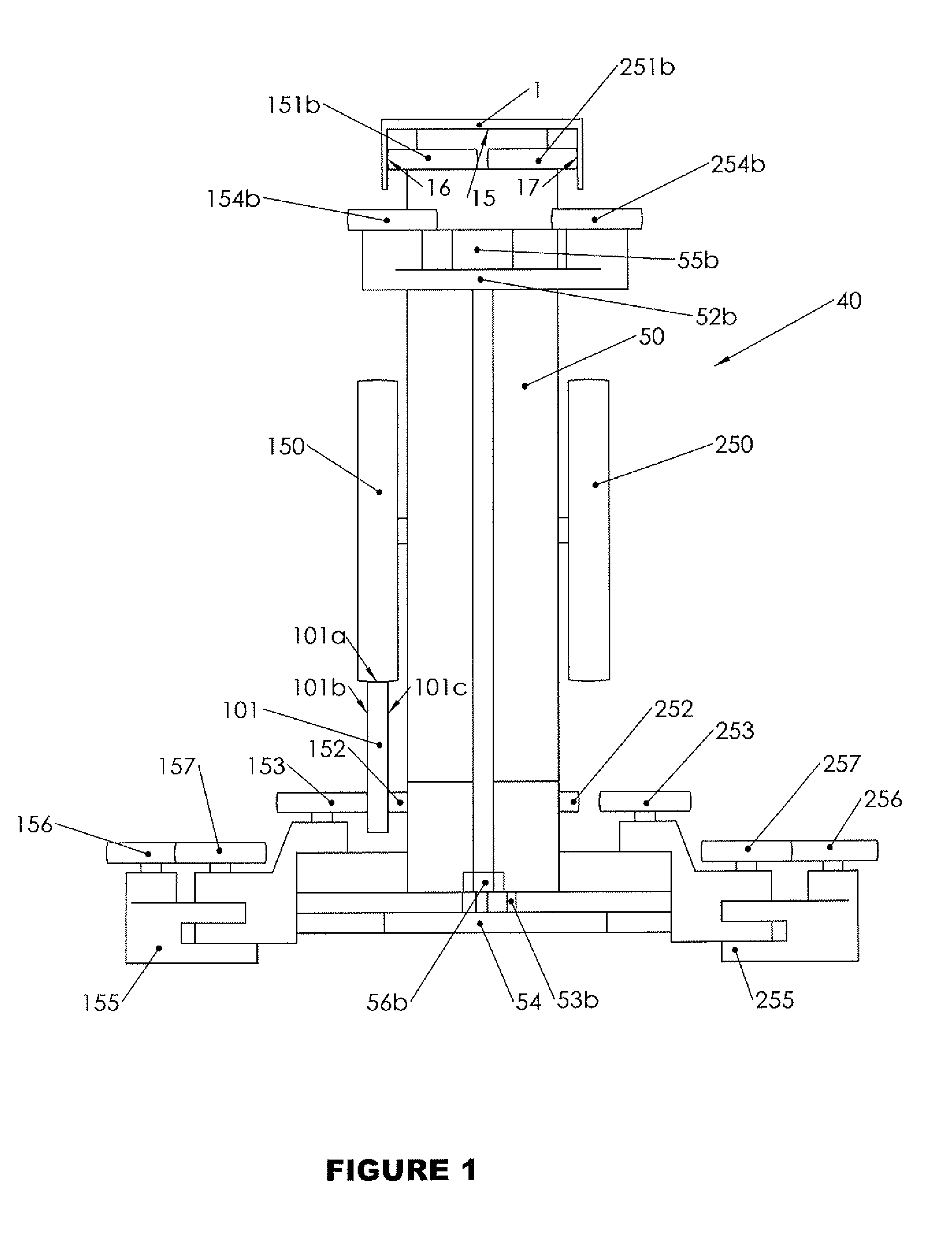
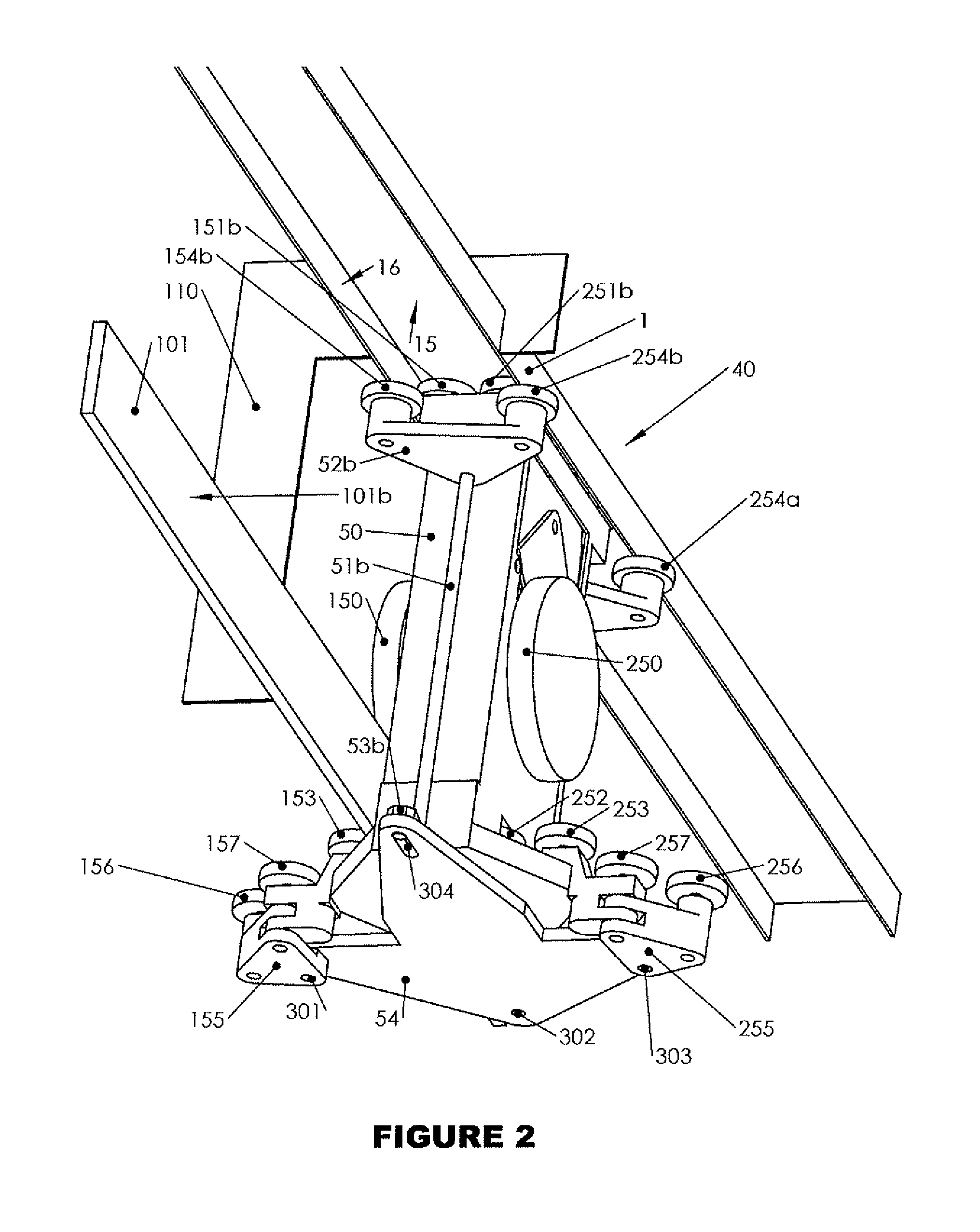
[0031]In FIG. 1 a preferred embodiment of a bogie is shown on a straight track section consisting of an upper u-shaped track member, the first track member 1, and a lower track member, referred to as the second track member 101, in this case arranged to the left in the direction of travel. These first 1 and second 101 track members are fixedly connected to each other, for instance using ribs (110, see FIG. 2) and preferably enclosed in a u-shaped cover with a downwards facing opening (not shown).

[0032]A bogie 40 has a bogie frame 50 holding left and right load bearing wheels 150, 250. In the shown embodiment, the left load bearing wheel 150 is in contact with the upwards facing surface 101a of the left second track member 101, thus transferring the downwards directed force from the bogie to the track. The bogie 40 is provided with upper guide wheels 151a, 151b...


PUM


Abstract

The present invention includes a track (1, 101) of a track system with straight, transition, curved, and switch track sections. The invention further comprises bogies (40) for vehicle cabins suspended under the track. Track sections of the track have an upper rail (1) and one or two lower rails (101, 201). Further, a bogie (40) has fore and aft sets of upper guide and switch wheels (151, 251, 154, 254), and one set of lower guide and switch wheels (152, 153, 252, 253, 156, 157, 256, 257). The bogies (40) also have one left and/or one right load bearing wheel (150, 250) and one drive wheel facing upwards and engaging a downwards directed drive wheel running surface (15) of the upper rail. Each set of lower guide wheels consist of left and right wheel pairs (152, 153, 252, 253) so that transition sections can be passed without moving any parts of the bogie (40). Switch wheels (154, 254, 156, 157, 256, 257) are separated from guide wheels so that they can be positioned according to the preferred direction of travel well before reaching a switch.

Description

FIELD OF THE INVENTION[0001]The present invention relates to a track and bogie for wheel based suspended vehicles. Vehicles provided with at least two of said bogies form together with said track a transportation system. In particular the invention is useful for public transportation often denoted as PRT (personal rapid transit).BACKGROUND OF THE INVENTION[0002]The problems with transporting the large and increasing number of people living in cities are well known. Public transportation with large vehicles in the form of metro, trolley and buses all have the problem with people having to wait for vehicles to arrive and then stop at all stations during the trips. Cars offer the flexibility of a personal trip but have problems with pollution, accidents, congestion and land use. A transit system which offers the flexibility of the car without its drawbacks is widely known as PRT.[0003]Many PRT systems have been described and patented. These systems can be characterized as having rotati...

Claims


Application Information

Patent Timeline
IPC IPC(8): B61B3/00B61F3/00B61B3/02
CPCE01B25/22B61B13/04B61B3/02
Inventor GUSTAFFSON, BENGT
Owner SUPRAWAYS
Why Eureka
Try Eureka