Constant velocity joint of tripod type

a constant velocity joint and tripod technology, applied in the direction of yielding coupling, rotary machine parts, metal-working hand tools, etc., can solve the problems of large manufacturing cost, relative large friction between the faces, and high manufacturing cost, so as to reduce contact surface, reduce manufacturing cost, and simple and durable structure

Active Publication Date: 2011-02-01
WIA CORP
View PDF30 Cites 3 Cited by
  • Summary
  • Abstract
  • Description
  • Claims
  • Application Information

AI Technical Summary

Benefits of technology

[0013]One object of the present invention is to provide a tripod type constant velocity joint which has a simple and durable structure and also is effective and reliable in operation, in which the joint includes, among other members, plural (e.g., three) trunnions each having a pair of cylindrical protrusions protruded a predetermined distance from the outer surface of the trunnion in a direction generally perpendicular to the axis of the corresponding trunnion. These cylindrical protrusions provide a reduced contact surface between the trunnion and the inner face of the corresponding inner roller, and thus, reducing the frictional spinning force acting on the contact ellipse made between the outer face of the trunnion and the inner face of the inner roller, due to the pivotal sliding movement of the trunnion axis known in the art.
[0014]Another object of the present invention is to provide a tripod type constant velocity joint having a sufficient lubrication mechanism between the inner race and the trunnion, and between the outer roller, the needle rollers, and the inner roller, to minimize the rolling resistance when rotating with any joint angle present.
[0015]A further object of the present invention is to provide a tripod type constant velocity joint which as a reliable structure and easy to be assembled. The joint includes, among other members, plural trunnions each having a pair of opposing cylindrical protrusions each protruded a predetermined distance from the outer surface of the trunnion in a direction generally perpendicular to the axis of the corresponding trunnion and each having spherical outer surface, and a pair of grooves formed on the bottom portion of the inner roller at two opposing locations corresponding to the pair of cylindrical protrusions to facilitate assembling the trunnion to the inner roller through the grooves. In certain preferred embodiments, each of the two opposing bottom grooves of the inner roller has an elliptical shape which can facilitate assembling the inner roller into the trunnion as the assembly is made with the inner roller tilted to a predetermined degree. This is because the elliptical shape of the two opposing bottom grooves of the inner roller corresponds to the outer surface of the two opposing protrusions of the trunnion when they are tilted with respect to each other as the spherical outer surface of the protrusions is projected to an elliptical shape when viewed from the tilted angle of the inner roller. This particular arrangement can reduce stress-concentrations typically occurring at the edge portions of the bottom grooves of the inner roller during the assembly process, and thus, can also prevent a potential plastic deformation of the inner roller during the assembly process of pressing the trunnion into the inner roller. As a result, an extra manufacturing or tooling cost, typically required for the assembly, can be reduced.

Problems solved by technology

Thus, a relatively large friction occurs between the faces.
Moreover, for manufacturing the constant velocity joint of FIG. 4, there are considerable difficulties not only to machine a complex spherical surface defined by a curvature of a longitudinal cross-section of the trunnion 18′ formed by radius r2 and R and the ellipse shape 18′ defined as a longer diameter A and a shorter diameter B, but also to measure the trunnion 18′ having a complex three dimensional profile, in terms of both inspection and quality control.
These difficulties cause the contact pattern mentioned above to be inconsistent in terms of quality, which leads to high costs in manufacturing perspective and also to potential quality control issues.
Hence it is difficult for the roller assembly 19 to be smoothly rolled, and causes a significant rolling resistance.
As such, because the space is too narrow to accommodate sufficient grease in the circumferential and axial direction, it is difficult for the grease to be introduced into the space.
This becomes more problematic when the grease is in high density condition, for example, during the initial driving stage of automobile particularly at a cold outside temperature, which causes a significant rolling resistance in the drive system.

Method used


Image

  • Constant velocity joint of tripod type
  • Constant velocity joint of tripod type
  • Constant velocity joint of tripod type

Examples


first embodiment

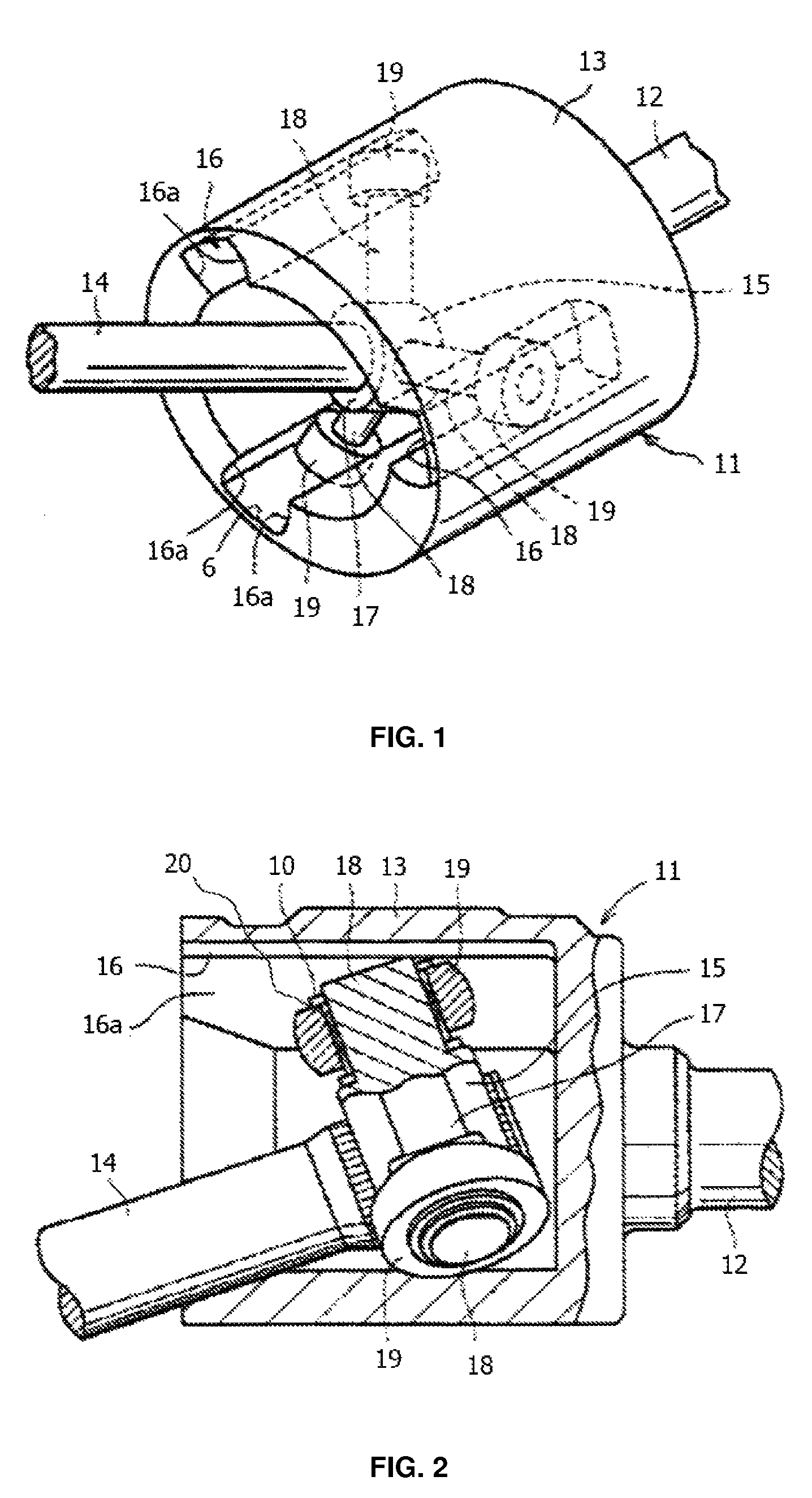
[0083]FIG. 5 shows cross-sectional views of a tripod joint constant velocity joint 1 according to the present invention; in which FIG. 5(a) is a cross-sectional view taken vertical to the second rotating shaft, and FIG. 5(b) is a side cross sectional view taken in an axial direction.

[0084]A tripod joint 1 shown in FIG. 5 comprises a hollow cylindrical housing 2 with one end defining an opening, and the other end secured to an end of a first rotating shaft 9 serving as a drive shaft or the like, and a tripod secured at one end of a second rotating shaft 8 which serves as a driven shaft or the like on the wheel side. Three grooves 10 are formed on the inner surface of the housing 2 in a configuration axially extending and equally spaced about the longitudinal axis of the housing. The grooves 10 are recessed from the inner surface outwardly in radial direction of the housing 2.

[0085]A tripod 7 is secured at one end of a second rotating shaft 8 with a ring-type boss 11 for supporting th...

second embodiment

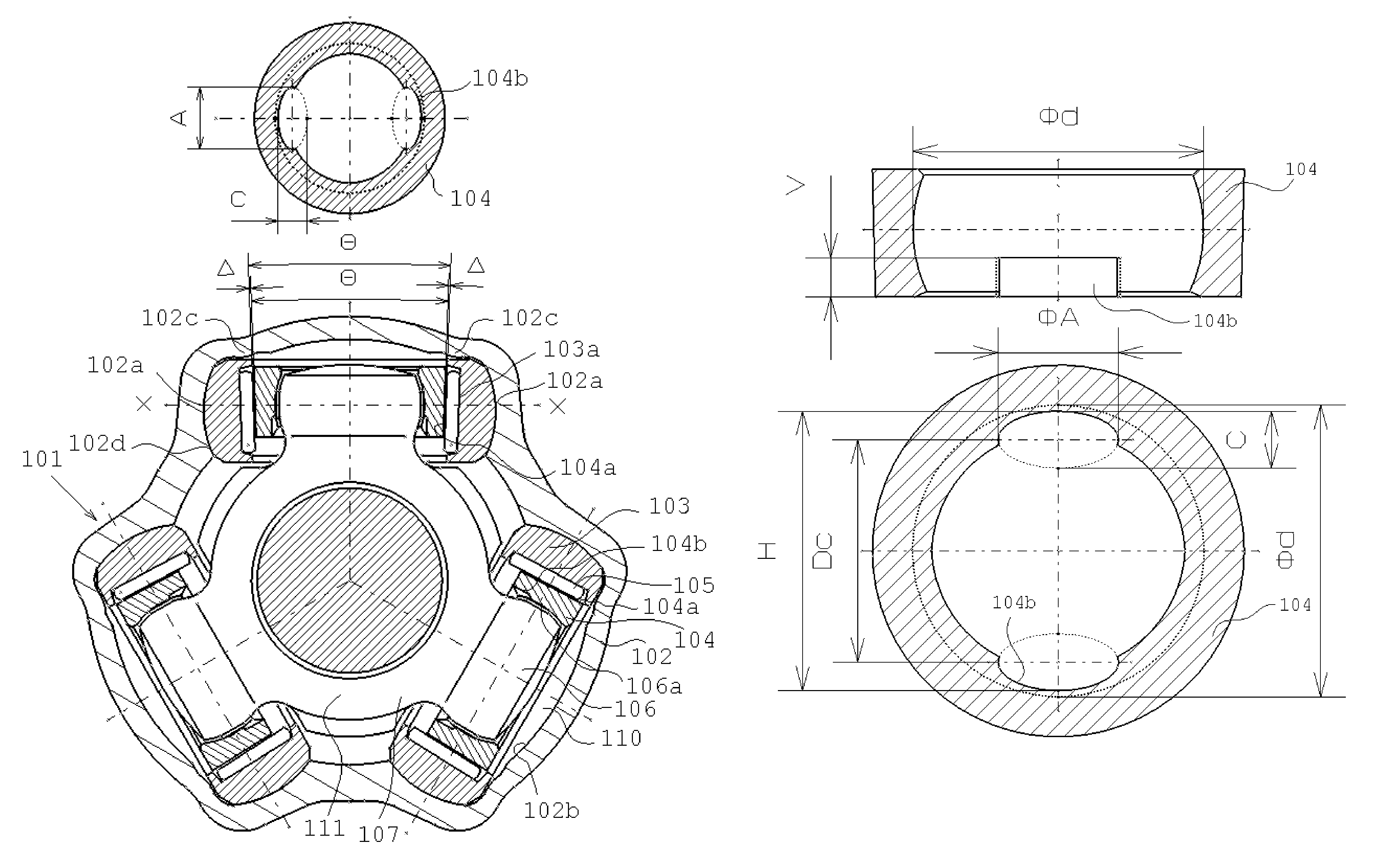
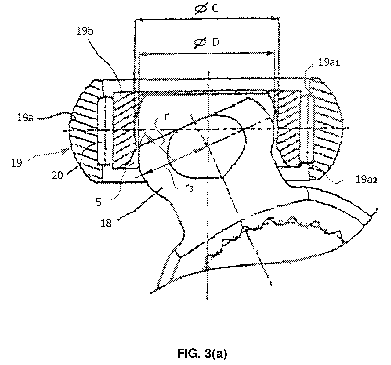
[0096]FIG. 6 illustrates the invention in which each trunnion 6 has a pair of cylindrical protrusions 6a with a diameter φA. The two protrusions 6a are disposed in the X-X direction of receiving a load and respectively protruded along the axis normal to the axis of the trunnion 6 by a height H1. The two protrusions 6a together define a generally spherical end surface with a diameter φD. Each trunnion 6 includes a pair of flat surfaces 6b in the Z-Z direction of not receiving a load, respectively, in order to diminish the spin moment and make grease flow easily in axial and circumferential direction and for enhancing an initial lubrication of the joint.

[0097]With reference to FIG. 7, the third embodiment is described herein. This embodiment is similar to the first and second embodiments described above. The difference of this embodiment shown in FIG. 7 from the above embodiments is that the central portion (φA1) of the spherical surface of the cylindrical protrusion 6a protruded from...

fourth embodiment

[0098]With reference to FIG. 8, the fourth embodiment is described herein. This embodiment is also very similar to the above described embodiment as shown in FIG. 6. The difference of this embodiment from that shown in FIG. 6 is that the trunnion 6 has a cylindrical protrusion 6a in the X-X direction of receiving the load, however, the protrusion 6a having an elliptical shape which defines a longer diameter B2 and shorter diameter A2.


PUM

PropertyMeasurementUnit
sizeaaaaaaaaaa
velocityaaaaaaaaaa
angleaaaaaaaaaa

Abstract

A constant velocity joint includes: a hollow housing fixed to a first rotating shaft, an inner face of the housing including a plurality of guide grooves; and a tripod disposed at an end of a second rotating shaft, having a plurality of trunnions each positioned in a corresponding guide groove; and an inner roller mounted to each trunnion, an outer roller mounted on each inner roller. Each trunnion includes an a spherical surface in a circumferential area subjecting to the load, and a cylindrical protrusion protruded from the spherical surface of the trunnion, the cylindrical protrusion having an spherical contact surface at its distal end with a gap between the trunnion and the the respective inner roller, and the inner face of each inner roller includes a pair of guide grooves for receiving the cylindrical protrusions.

Description

REFERENCE TO RELATED APPLICATION[0001]The present application is a continuation-in-part of U.S. patent application Ser. No. 11 / 750,138, entitled “CONSTANT VELOCITY JOINT OF TRIPOD TYPE” and filed on May 17, 2007, which was filed by the same applicant and assigned to the same assignee as the present application, the content of which is incorporated herein by reference in its entirety.FIELD OF THE INVENTION[0002]The present invention relates to a constant velocity joint of tripod type, which is disposed between a drive shaft and a driven shaft coupled to each other and typically used in a drive axle of, for example, an automobile for transmitting rotational torque between the rotating shafts.BACKGROUND OF THE INVENTION[0003]Tripod type constant velocity joints are well known in the automobile industry as one type of constant velocity joints used in the drive system of automobiles to transfer a uniform torque and a constant speed, while operating with a wide range of joint angle. For i...

Claims


Application Information

Patent Timeline
Patent Type & Authority Patents(United States)
IPC IPC(8): F16D3/26
CPCF16D3/2055Y10T29/5397Y10S464/905F16D2003/2026
Inventor OH, SEUNG TARK
Owner WIA CORP
Why Eureka
Try Eureka