Mirror system and method for acquiring biometric data

a mirror system and biometric data technology, applied in the field of mirror systems and methods for acquiring biometric data, can solve the problems of inability to solve the motion blur problem so far, inability to acquire images suitable for iris recognition, and small field of view and small depth of field, etc., to achieve high resolution

Active Publication Date: 2012-05-24
EYELOCK
View PDF0 Cites 39 Cited by
  • Summary
  • Abstract
  • Description
  • Claims
  • Application Information

AI Technical Summary

Problems solved by technology

The acquisition of images suitable for iris recognition is inherently a challenging problem.
This results in a small field of view and a small depth of field.
There is therefore a need to scan very quickly or else the person will have moved out of the capture volume or the subject's motion will cause a blur.
In the current state of the art, attempts to resolve this problem comprise using a flat mirror to scan but such attempts have not so far resolved the motion blur problem, especially when the camera is zoomed in.
The image motion in terms of pixels / second is very high which makes it very difficult to obtain high quality imagery with prior art systems in these situations.
Multiple cameras and lenses covering a larger volume is an obvious solution, but it requires the expense of additional cameras, optics and processing.
However approaches that point mirrors in such a fashion have to handle one or more key problems, namely: (i) the time latency involved in moving the camera to a location, (ii) vibration of the mirror and the resulting settling time of the mirror as it stops and starts motion, (iii) the complexity of the mechanical arrangement, (iv) the reliability, longevity and expense of the opto-mechanical components for such a moving assembly.
The problem with that approach is that it is very expensive or physically impossible to use such a mechanism to point at 2 or 3 places in a scene at a very high rate—for example, 5-50 times a second.
In addition, there is substantial settling time for the mirror or camera to stop vibrating as the mirror or pan / tilt assembly stops before imagery is acquired, so essentially it makes it almost physically impossible to scan at such high rates.

Method used


Image

  • Mirror system and method for acquiring biometric data
  • Mirror system and method for acquiring biometric data
  • Mirror system and method for acquiring biometric data

Examples


Embodiment Construction

[0021]While the invention is capable of many embodiments, only a few embodiments are illustrated in detail herein.

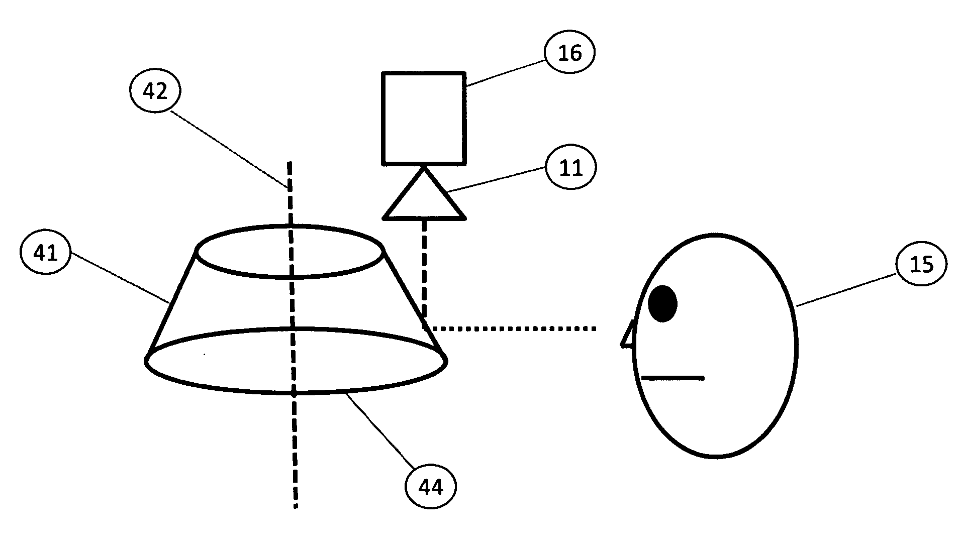
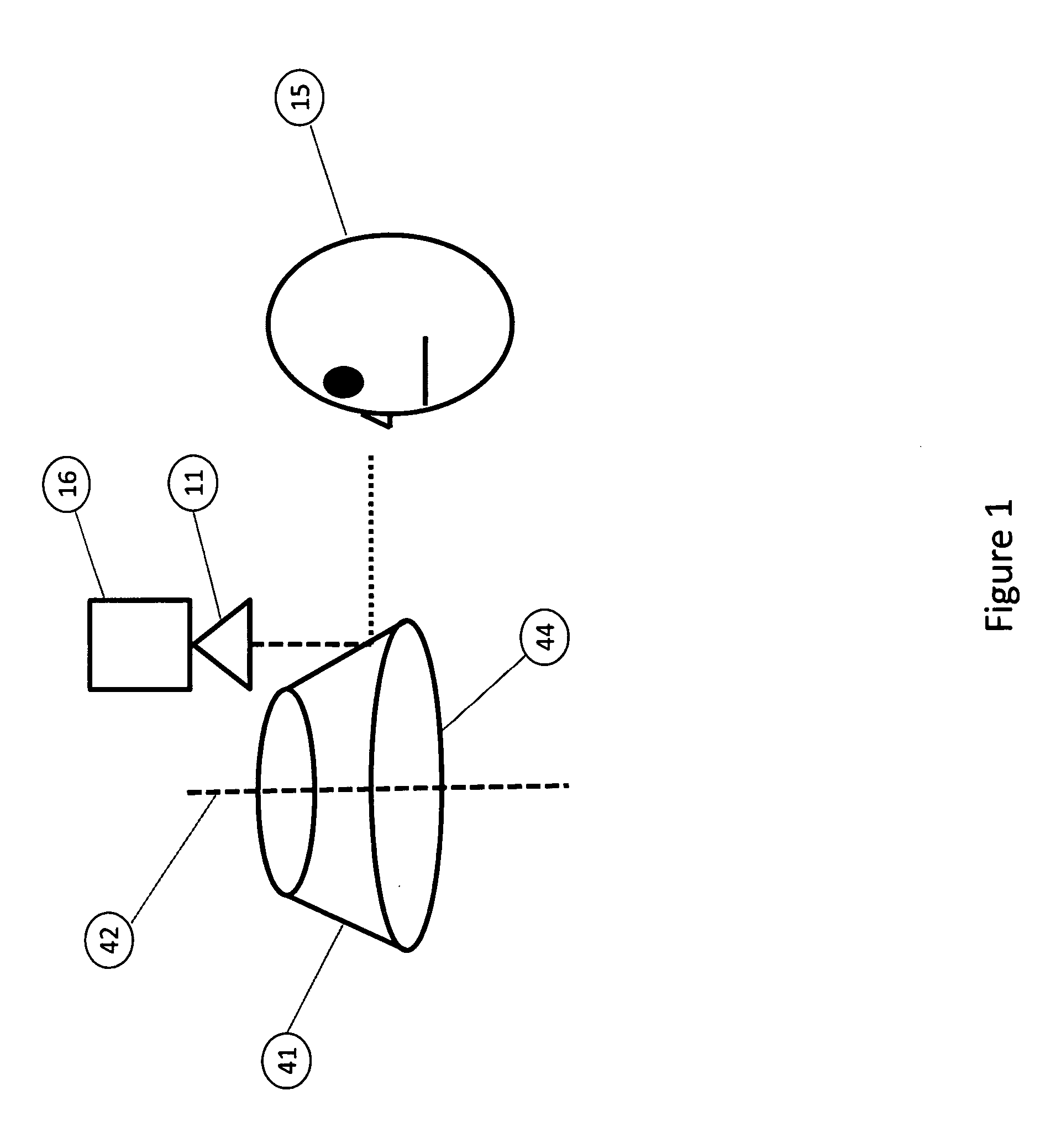
[0022]FIG. 1 illustrates an embodiment of the invention wherein a first non-flat mirror section 41 is rotated about axis 42 (motor not illustrated), and a second non-flat mirror section 44 is also rotated about axis 42 by the same motor. The lens 11 of the camera 16 receives an image of the subject 15 reflected off surface 44 to the lens 11.

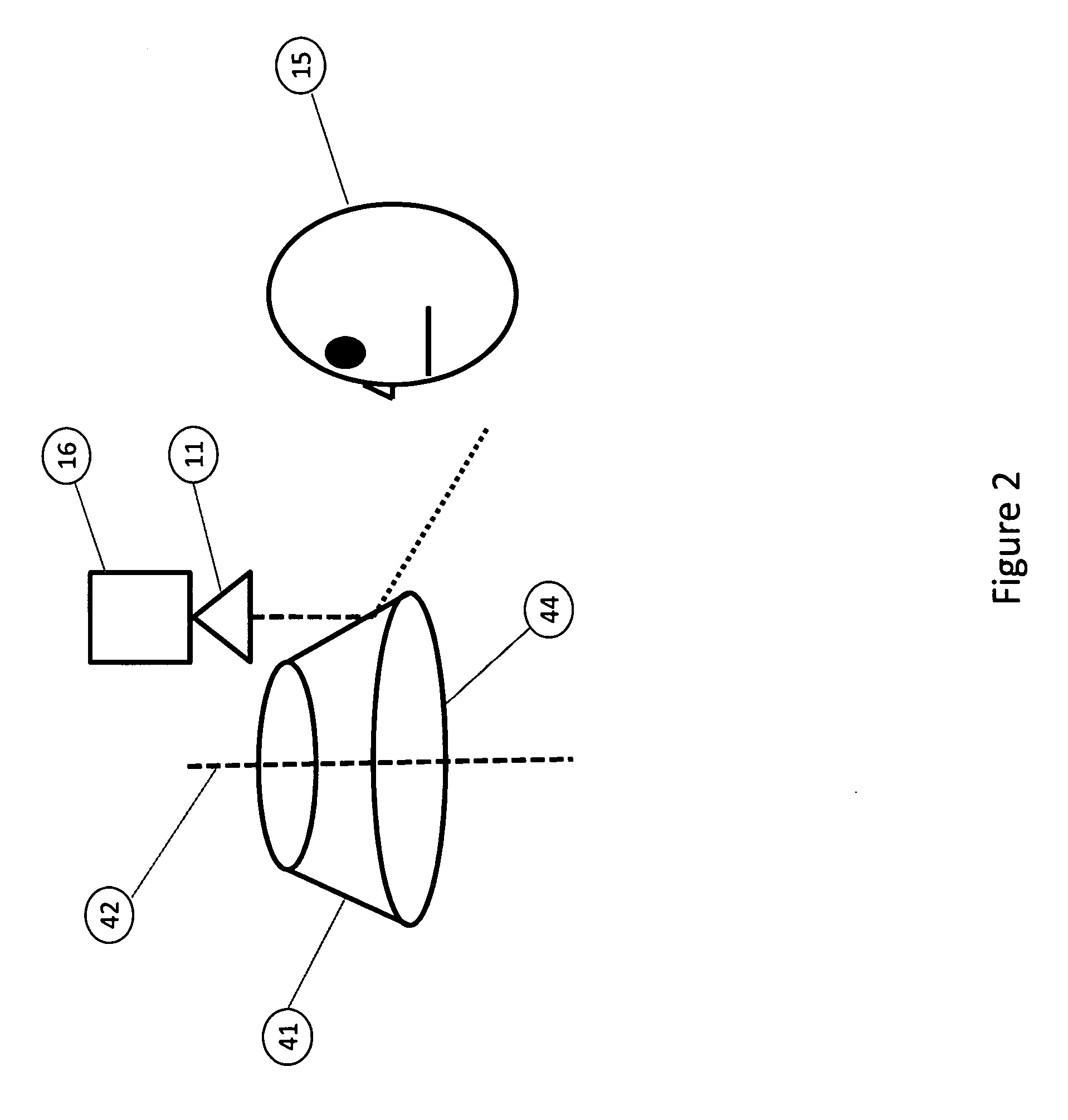
[0023]FIG. 2 illustrates the system of FIG. 1 at a different time instant at which an image of the subject 15 is reflected off of surface 41 and a different portion of the subject is reflected off mirror surface 41 to the lens.

[0024]FIG. 3 illustrates a set of three tiles 61-63, which are sections of the subject where the camera imagery points successively.

[0025]The following is a general description of a system and method according to the invention. An image is acquired using a camera system 10, 11, or any other image recording devic...


PUM


Abstract

A system and method for obtaining biometric imagery such as iris imagery from large capture volumes is disclosed wherein a substantially rotationally symmetric mirror such as a cone or sphere is rotated at a constant velocity about a central axis.

Description

CROSS-REFERENCE TO RELATED APPLICATIONS[0001]This application claims priority from provisional application 60 / 969,607, filed Sep. 1, 2007, which is hereby incorporated by reference. This International Application is also related to International Application Serial No.: PCT / US08 / 74737 (Attorney Docket GLOB0010-500), filed on even date herewith by the same applicant, which is hereby incorporated by reference.BACKGROUND OF THE INVENTION[0002]This invention relates to systems and methods for acquiring biometric and other imagery, biometric acquisition, identification, fraud detection, and security systems and methods, particularly biometric systems and methods which employ iris recognition with a camera having a field of view. More particularly the invention relates to systems and methods for very quickly acquiring iris imagery within a wide capture volume.[0003]Iris recognition systems have been in use for some time. The acquisition of images suitable for iris recognition is inherently...

Claims


Application Information

Patent Timeline
Patent Type & Authority Applications(United States)
IPC IPC(8): H04N7/18
CPCH04N7/18
Inventor HANNA, KEITH J.RIDDLE, GEORGE HERBERT NEEDHAMHIRVONEN, DAVID JAMESSLINEY, DAVID HAMMOND
Owner EYELOCK
Why Eureka
Try Eureka