Method and arrangement in a relay node and a controlling node

a technology of relay node and controlling entity, applied in multiplex communication, multiplex frequency, assessment restriction, etc., can solve the problems of affecting the performance of the controlling node, and affecting the broadcasting of system information, etc., to achieve better use of radio resources, increase peak rate, and improve capacity

Active Publication Date: 2012-05-24
TELEFON AB LM ERICSSON (PUBL)
View PDF6 Cites 24 Cited by
  • Summary
  • Abstract
  • Description
  • Claims
  • Application Information

AI Technical Summary

Benefits of technology

[0023]One advantage of the present invention is that the node controlling the Un / Uu subframe allocation is provided with the information needed to make an improved choice of subframe allocation for the Un and Uu interfaces. This improved, better-informed allocation process leads to better use of the radio resources and can bring higher capacity, increased peak rates, improved fairness etc, depending on what the objective is.
is that the node controlling the Un / Uu subframe allocation is provided with the information needed to make an improved choice of subframe allocation for the Un and Uu interfaces. This improved, better-informed allocation process leads to better use of the radio resources and can bring higher capacity, increased peak rates, improved fairness etc, depending on what the objective is.

Problems solved by technology

To do so could cause severe self-interference, since Uu and Un transmissions are performed within the same frequency.
It could potentially take several seconds before such a change of system information broadcast is applied in the UEs.
However, there is currently no mechanism defined for how the controlling node, e.g. donor eNB, should determine the relay subframe configuration.

Method used


Image

  • Method and arrangement in a relay node and a controlling node
  • Method and arrangement in a relay node and a controlling node
  • Method and arrangement in a relay node and a controlling node

Examples


Embodiment Construction

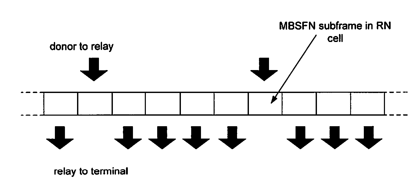
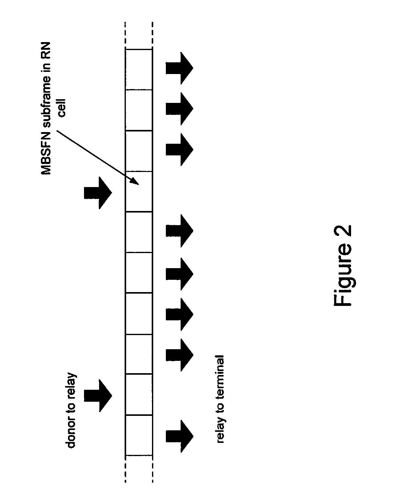
[0032]There is currently no mechanism defined for how the relay node should help the node controlling the relay subframe configuration, e.g. the donor eNodeB, in its decision, nor definitions for the types of information the relay node should provide to the donor eNB in making a decision if a change or update of the subframe configuration should be beneficial.

[0033]In order to configure an optimal relay subframe allocation, depending on what the system aims to achieve in terms of coverage, peak rates, capacity etc., there is first of all a need to have the necessary information available in the node controlling the Un / Uu configuration. This information could, among other things, include the load in different relays, the load coming from UEs directly served by the donor eNB, the link qualities of the Un link(s), the link qualities of the Uu link(s) etc, and combinations of these quantities. Once this information is available to the controlling node, the subframe configuration decisio...


PUM


Abstract

According to various embodiments, a method is provided at a relay node for enabling subframe allocation between a backhaul link and an access link of the relay node. The relay node is connected to a controlling entity via the backhaul link, and is connectable to at least one user equipment via the access link. The relay node receives a trigger or configuration information from the controlling entity from the controlling entity. Based on the received trigger or configuration information, the relay node sends information to the controlling entity, indicating a resource utilization of the access link and / or indicating a quality of the access link.

Description

TECHNICAL FIELD[0001]The present invention relates generally to methods at a relay node and a controlling entity, and to a corresponding relay node and a controlling entity. In particular, the invention relates to subframe allocation for a relay node.BACKGROUND[0002]3GPP (the 3rd Generation Partnership Project) is currently standardizing release 10 of the Long Term Evolution (LTE). LTE release 10 and beyond is also referred to as LTE-Advanced.[0003]3GPP LTE release 10 includes support for relays. A relay is an intermediate network node which relays information between one or more mobile terminals, e.g. LTE user equipments (UEs), and another base station, commonly referred to as the donor base station. The donor may be an evolved NodeB (eNB) and may also be referred to as a donor eNB or DeNB. The relay does not have its own fixed backhaul connection, but is instead connected to the core network via a wireless communication link to the donor base station. Thus, relays may be deployed ...

Claims


Application Information

Patent Timeline
Patent Type & Authority Applications(United States)
IPC IPC(8): H04W48/18H04W72/04
CPCH04B7/155H04W84/047H04W72/0433H04B7/2606H04W72/29
Inventor MOBERG, PETERMILDH, GUNNAROSTERGAARD, JESSICAPERSSON, HAKAN
Owner TELEFON AB LM ERICSSON (PUBL)
Why Eureka
Try Eureka