Cutting tool and method of manufacturing machined product using the same

a cutting tool and a manufacturing method technology, applied in the direction of manufacturing tools, shaping cutters, metal working apparatuses, etc., can solve the problems of difficult thrust force of cutting force, and achieve the effect of reducing plastic deformation of constraining faces and excellent durability

Active Publication Date: 2012-05-24
KYOCERA CORP
View PDF17 Cites 8 Cited by
  • Summary
  • Abstract
  • Description
  • Claims
  • Application Information

AI Technical Summary

Benefits of technology

[0008]In the cutting tool according to the embodiment of the present invention, one of the two constraining faces constraining the cutting insert is formed substantially perpendicularly to the rotation axis of the holder. Therefore, compared to the conventional cutting tool in which the two constraining faces constraining the cutting insert are formed substantially line-symmetrically at the predetermined angle with reference to the rotation axis direction, the cutting tool of the present embodiment makes it difficult for the thrust force of cutting force to so act that the two constraining faces are expanded. This reduces plastic deformation of the constraining faces, thus having excellent durability.

Problems solved by technology

Therefore, compared to the conventional cutting tool in which the two constraining faces constraining the cutting insert are formed substantially line-symmetrically at the predetermined angle with reference to the rotation axis direction, the cutting tool of the present embodiment makes it difficult for the thrust force of cutting force to so act that the two constraining faces are expanded.

Method used


Image

  • Cutting tool and method of manufacturing machined product using the same
  • Cutting tool and method of manufacturing machined product using the same
  • Cutting tool and method of manufacturing machined product using the same

Examples


Embodiment Construction

[0015]

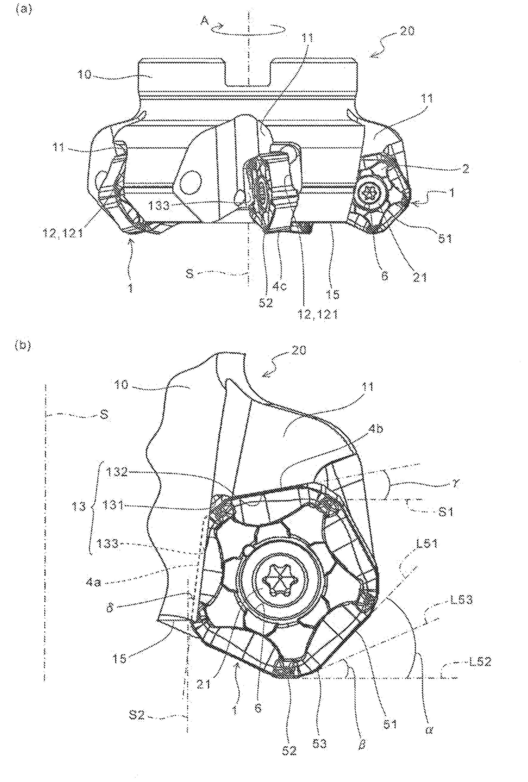
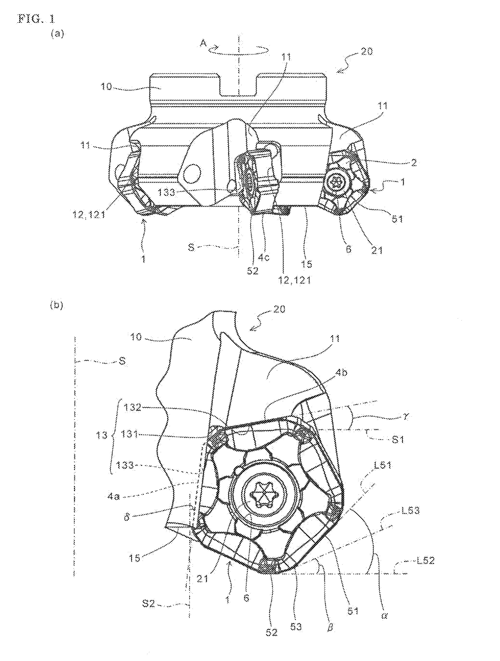
[0016]An embodiment of the cutting tool according to the present invention is described in detail below with reference to FIGS. 1 to 5. As shown in FIG. 1, the cutting tool 20 (rotary cutting tool) of the present embodiment includes a cutting insert (hereinafter referred to as “insert” in some cases) 1, and a holder 10 having at a front end part 15 thereof insert pocket 11 for attaching the insert 1 thereto. Firstly, the insert 1 and the holder 10 that are elements constituting the cutting tool 20 are described in detail.

[0017](Cutting Insert)

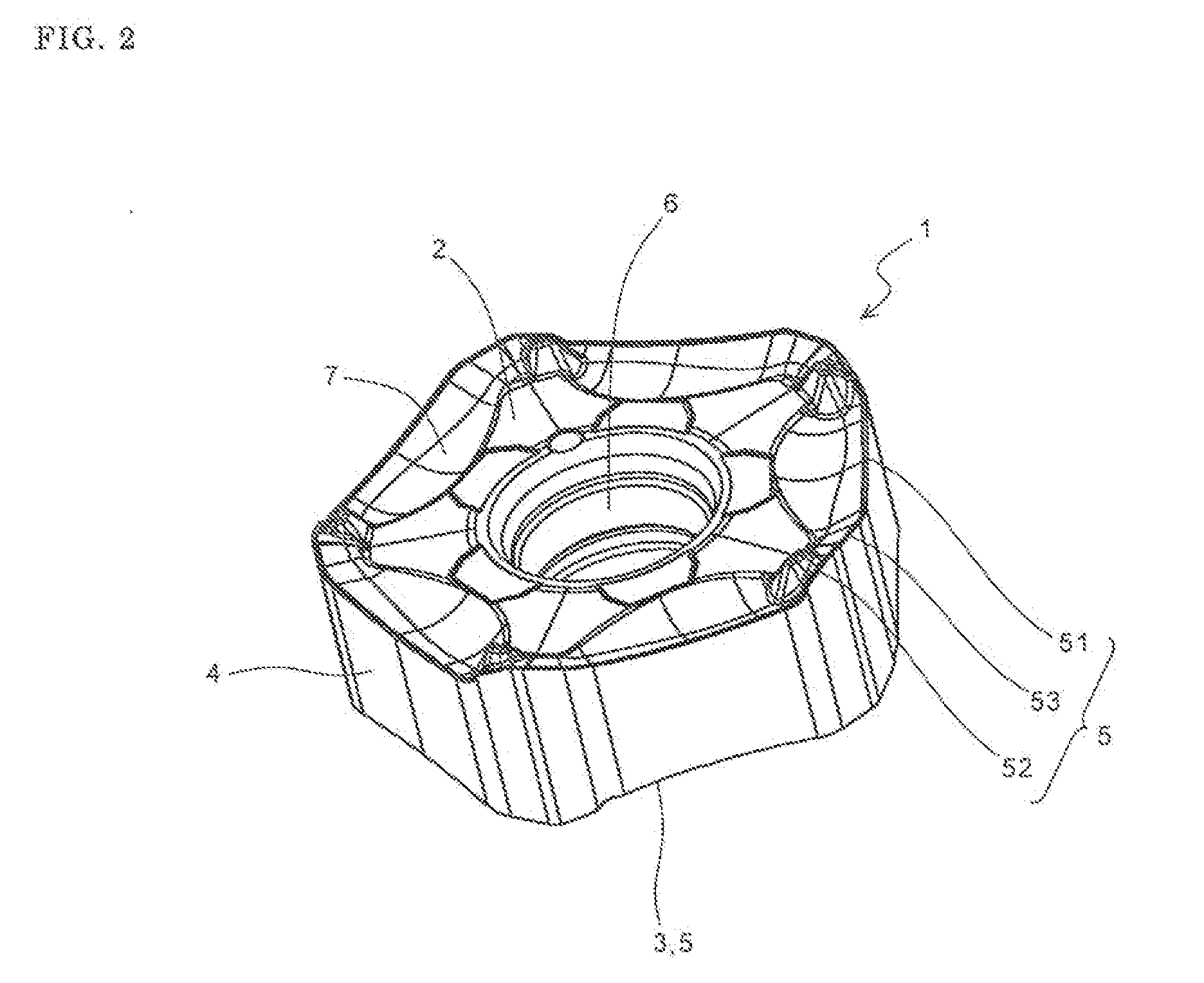
[0018]Referring to FIG. 2, each of the insert 1 includes a body part of a substantially polygonal plate shape. No particular limitation is imposed on the shape of the body part. That is, the body part may have a certain shape usually employed by those skilled in the art, such as triangle, quadrangle, pentagon, hexagon, and octagon in a top view. The present embodiment employs a substantially pentagonal shape having five long sides.

[0019]T...


PUM

PropertyMeasurementUnit
angleaaaaaaaaaa
angleaaaaaaaaaa
angleaaaaaaaaaa

Abstract

A cutting tool of the present invention includes a cutting insert and a holder having at a front end part thereof an insert pocket for attaching the cutting insert. The insert pocket includes a seating part including a seating face which is brought into contact with the lower surface of the cutting insert, and is inclined forward in a rotation direction of the holder as the seating face separates from the front end part of the holder; and a constraining part brought into contact with first and second side surfaces adjacent to each other among the side surface of the cutting insert. The constraining part includes a curved portion; a first constraining face which is connected to one end of the curved portion and extends perpendicularly with respect to the rotation axis of the holder as the first constraining face separates from the curved portion, or extends away from the front end part of the holder; and a second constraining face which is connected to the other end of the curved portion and extends toward the front end part of the holder in the direction away from the curved portion. A method of manufacturing a machined product using the cutting tool is provided.

Description

TECHNICAL FIELD[0001]The present invention relates to a cutting tool and a method of manufacturing a machined product using the same.BACKGROUND ART[0002]Conventionally, various considerations have been made to decrease cutting resistance in a cutting tool that uses cutting inserts by attaching them to insert pockets of a holder. For example, as in the case of Japanese Unexamined Patent Publication No. 2008-544872, the cutting resistance is decreased by inclining a ridge line of a major cutting edge of the cutting insert to make adjustments so that an axial rake angle of a major cutting edge has a positive angle, or by increasing a peripheral cutting edge angle of the major cutting edge.[0003]However, for example, when the peripheral cutting edge of the major cutting edge is increased, the cutting resistance is decreased because chip thickness is decreased, whereas a component force (thrust force) of a cutting force oriented rearward of a rotation axis is increased. Additionally, in ...

Claims


Application Information

Patent Timeline
Patent Type & Authority Applications(United States)
IPC IPC(8): B23C5/20B23C3/00B23C5/02
CPCB23C5/006B23C5/06B23C5/202B23C5/2213B23C2200/0444Y10T407/1924B23C2200/323B23C2210/168Y10T409/303808Y10T407/1906Y10T407/1908B23C2200/205
Inventor ISHI, HIROHISA
Owner KYOCERA CORP
Why Eureka
Try Eureka