
Hand-held manipulator with symmetrical grip

a technology of manipulators and symmetrical grips, which is applied in the direction of gear teeth, diagnostics, applications, etc., can solve the problems of complex devices, operator's inability to modify the grip of his/her hand on the handle, and precise operations in which the movements to be carried out are complex

Inactive Publication Date: 2012-05-24
DEXTERITE SURGICAL
View PDF5 Cites 6 Cited by
  • Summary
  • Abstract
  • Description
  • Claims
  • Application Information

AI Technical Summary

Benefits of technology

[0020]The object of the present invention is to design a manipulator in which the operator is able to apply to the manipulator in a simple and manual manner a relative axial rotational movement about the longitudinal axis of the connecting arm relative to the hand which holds the manipulator, without necessarily losing the permanent capacity for holding the tool in position and activating the control member(s) mounted on the handle to permit relative movements of the tool support and / or of the tool at the distal end of the connecting arm to be controlled.
[0024]According to a first embodiment, the gripping portion has a cylindrical revolution shape. This is the simplest shape, which is easily able to be implemented and adapted to any size of operator hand.

Problems solved by technology

These are intricate, precise operations in which the movements to be carried out are complex.
This requires the device to be complicated, however, by providing a motor or other mechanical system, mechanical connecting means and joints.
With the existing handles, the operator is not able to modify the grip of his / her hand on the handle, and the capacity for rotation of the handle is thus limited to a value of a few tens of degrees corresponding to the amplitude of possible movements of the wrist joint of the hand holding the manipulator.
This capacity for movement is clearly insufficient for the tool to carry out at the end of the manipulator all the operations generally envisaged.
Said device, however, has the drawback of not being able to orientate the forceps outside the longitudinal axis, nor to be able to apply to the forceps a specific rotation about the axis thereof when said axis is inclined outside the longitudinal axis of the manipulator.

Method used


Image

  • Hand-held manipulator with symmetrical grip
  • Hand-held manipulator with symmetrical grip
  • Hand-held manipulator with symmetrical grip

Examples


Embodiment Construction

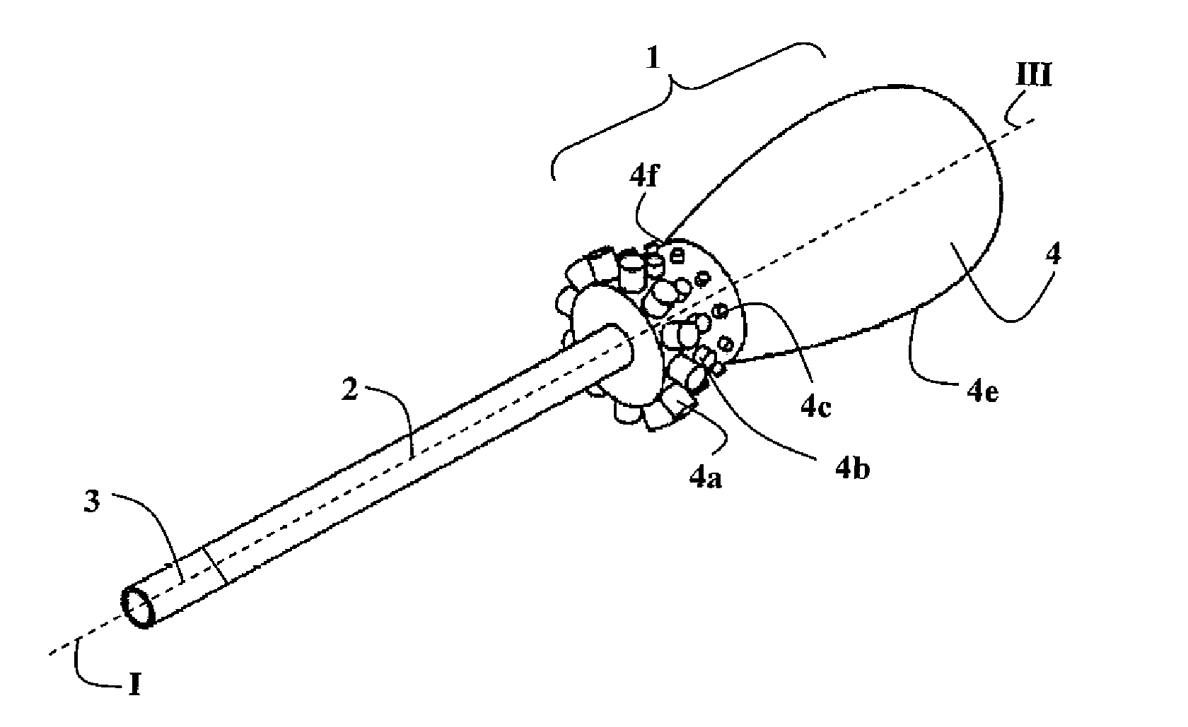
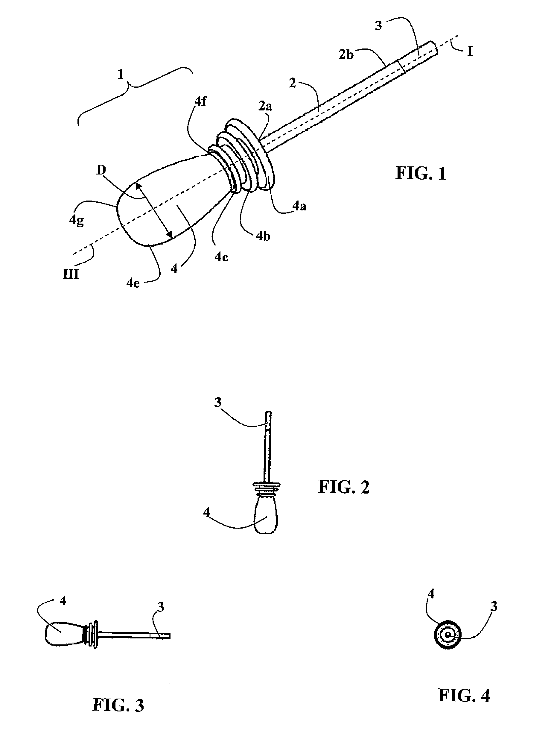
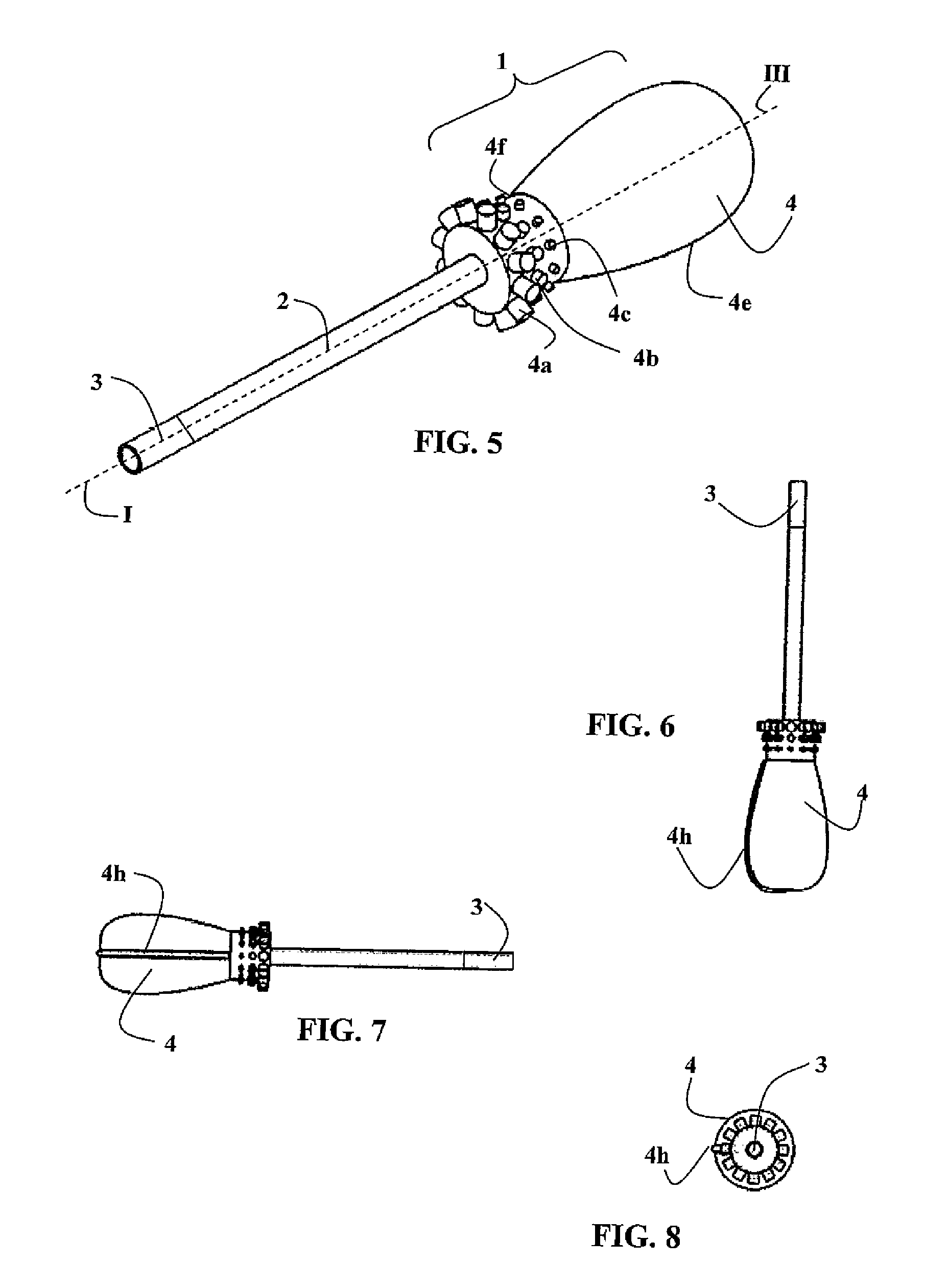
[0047]In the embodiments illustrated in the figures, a manipulator according to the invention comprises a control unit 1 having a handle 4 which is capable of being held by one hand.

[0048]The handle 4 carries at least one control member, for example three control members 4a, 4b and 4c, the control members being structured and arranged so as to be able to be activated by at least one finger of the hand holding the handle 4.

[0049]The manipulator comprises a connecting arm 2 extending along a longitudinal axis of the arm I, having a proximal end 2a and a distal end 2b.

[0050]The control unit 1 is mounted in the proximal end 2a of the connecting arm 2 and the handle 4 forms the proximal end of the manipulator.

[0051]In FIG. 9, the manipulator is illustrated in the position of use. As in the known devices, the connecting arm 2 passes into a trocar 7, providing the connection and passage into an opening 8 made in the body wall 9 of a patient.

[0052]A working unit 3 is mounted on the distal ...


PUM

PropertyMeasurementUnit
Timeaaaaaaaaaa
Angleaaaaaaaaaa
Massaaaaaaaaaa

Abstract

A hand-held manipulator includes a handle (4) fixedly mounted on the end of a connecting arm (2), the distal end (2b) of which carries a work unit (3). The handle (4) includes a grip section (4e) having a surface of revolution about a longitudinal handle axis (III), which is aligned with the longitudinal axis (I) of the arm. Control elements (4a-4c) are shaped in an annular structure near the distal end (4f) of the grip section (4e) so as to be accessible in any angular orientation of the hand holding the handle.

Description

TECHNICAL FIELD OF THE INVENTION[0001]The present invention relates to manipulation devices, permitting the movements of a manipulation instrument located inside an operating area to be controlled from outside the operating area.[0002]In particular, said manipulation devices permit a surgical tool to be positioned and controlled in applications for minimally-invasive surgery carried out by endoscopy.[0003]In said applications, it is necessary to be able to displace and control a surgical tool to carry out various operations such as providing a suture, tying a knot or delicate dissection of tissue. These are intricate, precise operations in which the movements to be carried out are complex.[0004]The invention relates more specifically to portable, articulated surgical manipulation devices in which a surgical tool is placed at the end of a portable manipulator, essentially having a connecting arm with a proximal end and a distal end. A proximal end of the connecting arm carries a cont...

Claims


Application Information

Patent Timeline
IPC IPC(8): A61B19/00
CPCA61B19/22A61B2017/00455A61B2017/0042A61B17/2909A61B2019/2269Y10T408/6764A61B17/8875A61B34/70A61B34/74
Inventor BARRIER, PASCALOLLAGNIER, JEREMYROSSET-LANCHET, REMI
Owner DEXTERITE SURGICAL
Learn More