
Control device and control method used for engine intake air-or-gas system

a control device and control valve technology, applied in the direction of electrical control, process and machine control, instruments, etc., can solve the problems of difficult detection of malfunction, malfunction or sticking of the egr control valve, and inability to detect valve malfunction

Active Publication Date: 2012-05-24
MITSUBISHI HEAVY IND LTD
View PDF53 Cites 13 Cited by
  • Summary
  • Abstract
  • Description
  • Claims
  • Application Information

AI Technical Summary

Benefits of technology

[0060]According to the present invention, a control device and a control method of a control valve which is used for an intake air-gas system of an engine can be supplied, wherein: the malfunction of the control valve used for the intake air-gas system can be detected even under the operation condition that the actual opening agrees with the target opening and the target opening is unchanged; and the control valve sticking attributable to a damage of the motor bearing can be prevented, the damage being caused by a lube-oil loss due to the condition that the opening of the EGR control valve is kept at a same constant level for a certain long duration of time.

Problems solved by technology

However, in each of Patent Reference 1 and Patent Reference 2, even in a case where the EGR control valve is out of order, the actual opening of the EGR control valve agrees with the target opening of the valve; thus, the malfunction of the valve cannot be detected under an operating condition that the target opening is not changed.
Above all, in a case where the target opening of the EGR control valve is 0, the EGR control valve with its own structure is provided with a function to press the valve toward the full closed direction; thus, the actual opening apparently follows the target opening so that it is difficult to detect the malfunction.
Thus, the damage of the motor bearing is caused by the loss of the lube-oil, and a risk of malfunction or sticking of the EGR control valve arises.

Method used


Image

  • Control device and control method used for engine intake air-or-gas system
  • Control device and control method used for engine intake air-or-gas system
  • Control device and control method used for engine intake air-or-gas system

Examples


Embodiment Construction

[0079]Hereafter, the present invention will be described in detail with reference to the modes or embodiments shown in the figures. However, the dimensions, materials, shape, the relative placement and so on of a component described in these modes or embodiments shall not be construed as limiting the scope of the invention thereto, unless especially specific mention is made.

[0080](First Mode)

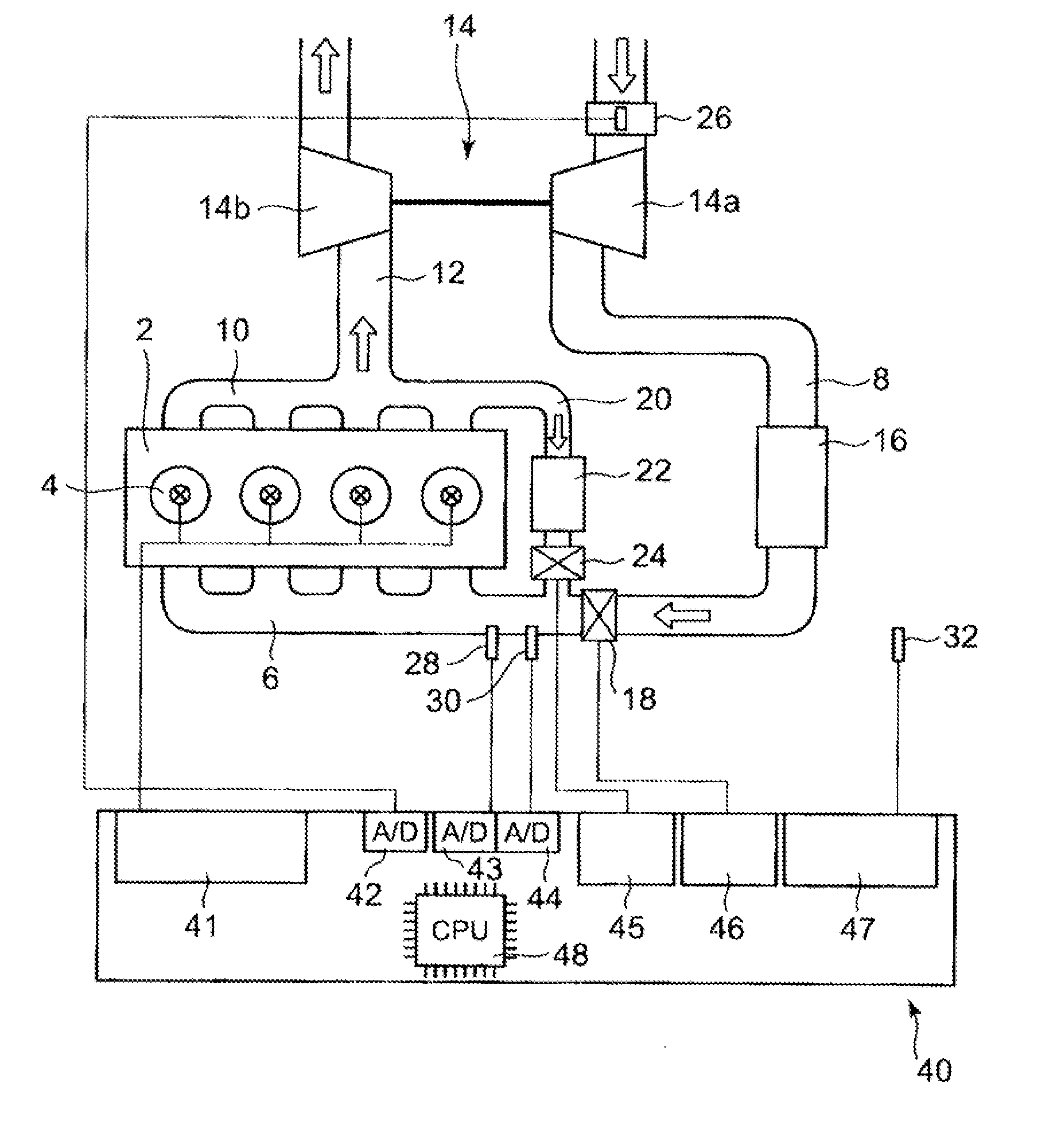
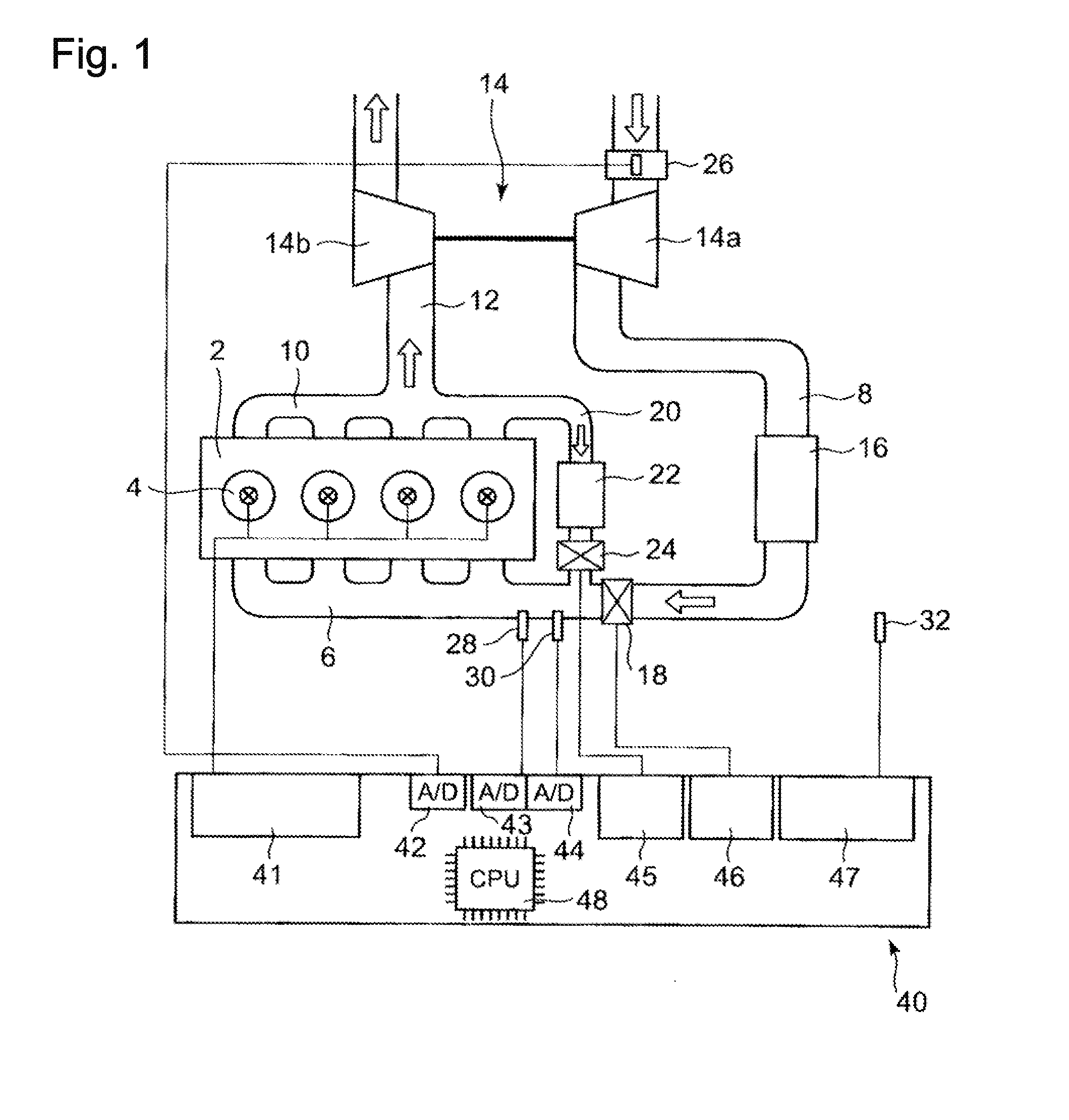
[0081]FIG. 1 shows an outline of an EGR device to which a control device of an EGR control valve according to a first mode of the present invention is applied. In FIG. 1, an engine 2 is a four stroke cycle diesel engine of four cylinders.

[0082]An intake air passage 8 joins the engine 2 via an intake manifold 6. Further, the engine is connected to an exhaust gas passage 12 via an exhaust manifold 10.

[0083]In the intake air passage 8, a compressor 14a of a turbocharger 14 is provided. The compressor 14a is driven by a shaft common to the compressor 14a and a turbine 14b as described later. In the ...


PUM


Abstract

A control device of a control valve used for an intake air-gas system of an engine, the device including, but not limited to: the control valve which is an intake air throttle valve provided in the intake air-gas system provided in the intake air-gas system of the engine to control the flow rate of intake air to the engine, or an EGR valve provided in the intake air-gas system of the engine to control the flow rate of EGR gas to the engine; and a control unit which determines a target opening of the control valve in response to the operation conditions of the engine, and controls the opening of the control valve so that the opening conforms with the target opening, wherein the control unit is configured so that, in a case where the target opening is maintained at a same level during over a fixed duration, the target opening is changed, in time, from the target opening which is determined in response to the operation conditions of the engine and controls the opening of the control valve, in order to prevent the control valve from being out of order as well as in order to detect a failure of the control valve.

Description

BACKGROUND OF THE INVENTION[0001]1. Field of the Invention[0002]The present invention relates to a control device and a control method of a control valve which is used for an intake air (an intake air-gas) system of an engine, the device being provided with:[0003]the control valve which is[0004]an intake air throttle valve provided in the intake air-gas system provided in the intake air-gas system of the engine to control the flow rate of intake air to the engine, or[0005]an EGR valve provided in the intake air-gas system of the engine to control the flow rate of EGR gas to the engine; and[0006]a control unit which determines a target opening of the control valve used for an intake air-gas system, in response to the operation conditions of the engine, and controls the opening of the control valve used for an intake air-gas system so that the opening conforms with the target opening.[0007]2. Background of the Invention[0008]As a technology reducing NOx in the exhaust gas emitted from...

Claims


Application Information

Patent Timeline
IPC IPC(8): F02D41/26F02D28/00
CPCF02D35/0007F02D41/0002F02D41/0052F02D41/0077F02D41/221F02M25/0726F02M25/0707F02M25/0727Y02T10/42Y02T10/47F02D2041/1409F02M26/05F02M26/22F02M26/23Y02T10/40F02D9/02F02D21/08F02D41/14F02D41/22
Inventor IDE, KAZUNARITAKAYANAGI, KOKUBO, HIROYOSHI
Owner MITSUBISHI HEAVY IND LTD
Learn More