
System and method for use in designing utility networks

a utility network and system technology, applied in the field of utility networks, can solve the problems of increasing the level of user involvement, requiring considerable knowledge and experience, and adding significant delay, cost, and inaccuracy to the utility network design process

Active Publication Date: 2012-05-24
GENERAL ELECTRIC CO
View PDF8 Cites 8 Cited by
  • Summary
  • Abstract
  • Description
  • Claims
  • Application Information

AI Technical Summary

Benefits of technology

"The patent describes a system and method for designing a utility network to provide a utility to a geographic area. The system uses an input interface to receive information about the area, identifies obstacles, and determines demand points and a source point for the utility. The system then generates a bill of materials indicating the equipment required to convey the utility from the source point to the demand point along a determined connection path. The technical effect of the patent is to provide a more efficient and effective way to design utility networks, taking into account obstacles and demand points, to minimize costs and improve reliability."

Problems solved by technology

Moreover, the user may be required to determine and select equipment appropriate for conveying the utility along the manually defined path, which requires considerable knowledge and experience on the part of the user.
The level of user involvement may add significant delay, cost, and inaccuracy to the utility network design process.

Method used


Image

  • System and method for use in designing utility networks
  • System and method for use in designing utility networks
  • System and method for use in designing utility networks

Examples


Embodiment Construction

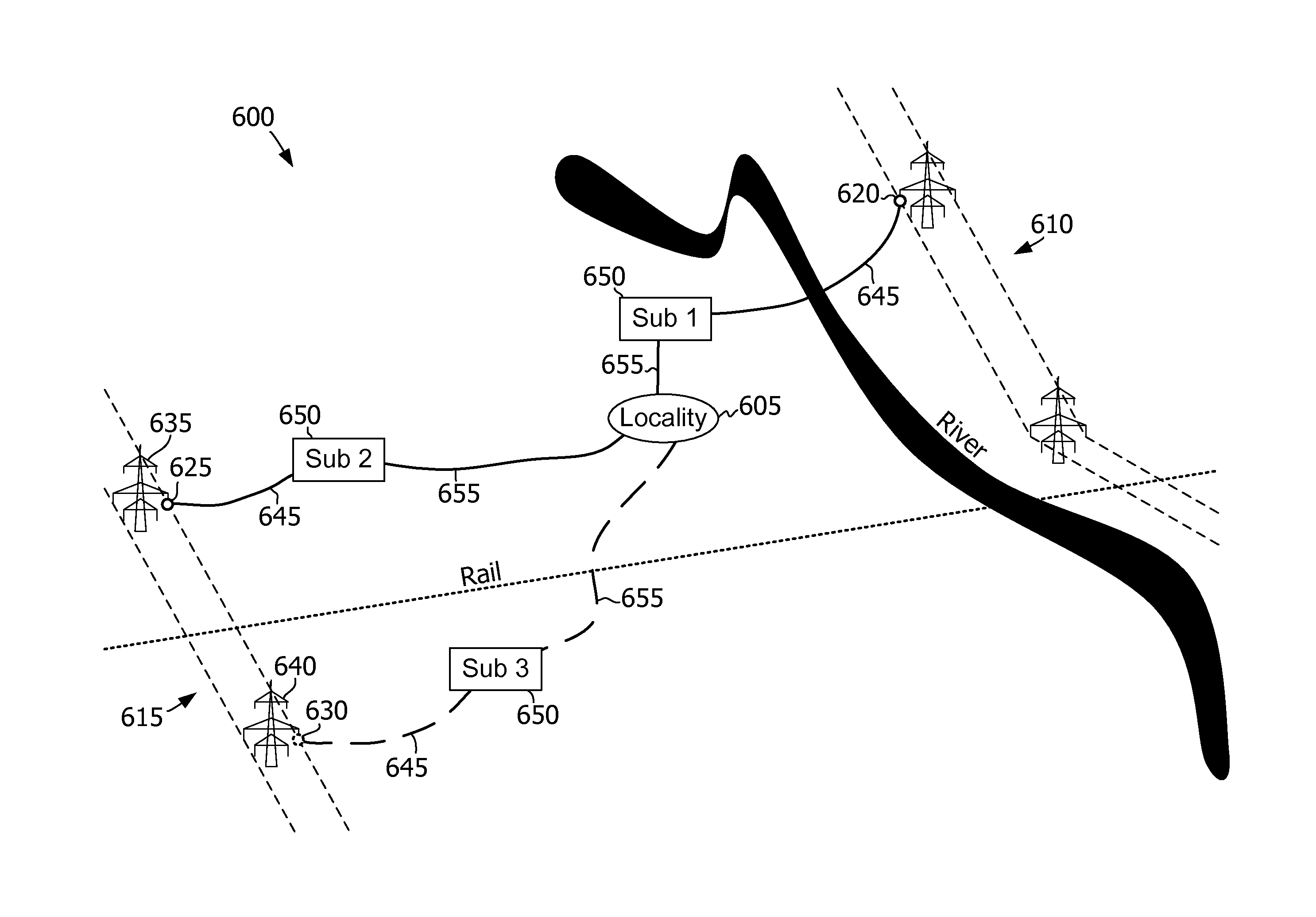
[0012]The embodiments described herein facilitate automating the design of a utility network, taking into account the presence of physical obstructions and constraints, such as regulatory constraints, environmental constraints, and demand constraints. As used herein, the term “utility” includes, but is not limited to only including, electricity, natural gas, water (e.g., fresh water, sewage, or drainage), television service, and / or wired or wireless telecommunication service.

[0013]A utility network is operable to convey a utility from one or more source localities, source lines, or source points, to one or more demand localities, demand lines, or demand points. For example, a source locality may include a utility generation facility or an existing utility network. A source line may include an existing utility transmission line or utility distribution line. A source point may include a utility distribution point (e.g., a substation and / or a transformer), a specific point within a uti...


PUM


Abstract

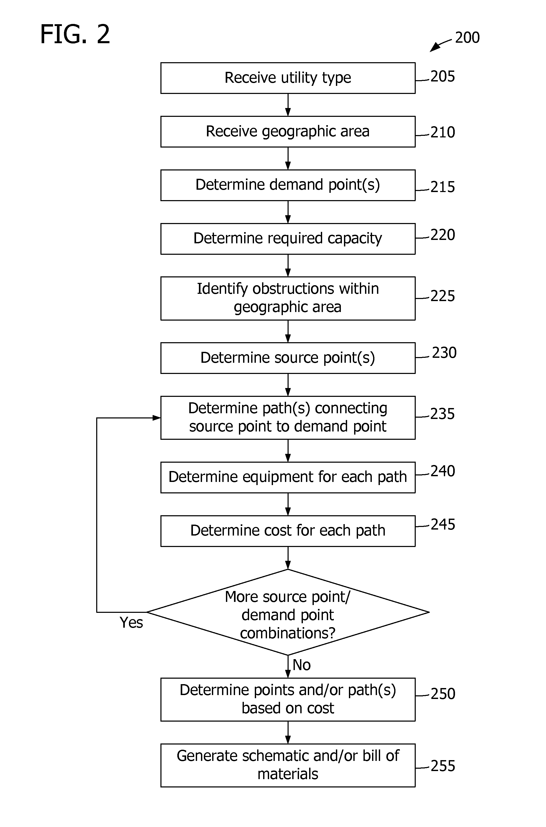
A method for use in designing a utility network to provide a utility to a geographic area. A computer system determines a demand point within the geographic area at which to provide the utility. The computer system also determines a source point to provide the utility to the utility network. A connection path through the geographic area is determined, connecting the source point to the demand point. In addition, a bill of materials may be generated, indicating a set of equipment required to convey the utility from the source point to the demand point along the determined connection path.

Description

BACKGROUND OF THE INVENTION[0001]The subject matter disclosed herein relates generally to utility networks and, more specifically, to systems and methods for use in designing a utility network.[0002]At least some known utility networks are used to convey a utility, such as electricity or natural gas, from a source point to a demand point. Further, at least some known software enables a user to specify a utility network design for a geographic area, and some provide an option to start with a preconfigured design. Even with a preconfigured design, such software generally requires the user to manually define a path along which to convey the utility. For example, the user may be required to route the utility around obstructions within a particular geographic area. Moreover, the user may be required to determine and select equipment appropriate for conveying the utility along the manually defined path, which requires considerable knowledge and experience on the part of the user. The leve...

Claims


Application Information

Patent Timeline
Patent Type & Authority Applications(United States)
IPC IPC(8): G06F17/50
CPCG06F17/509G06F30/18
Inventor ANDOJI, KAVITHAOZA, BHARGAV J.VEPAKOMMA, BHASKAR PRAVEENSADINEEDI, PREM SWAROOP
Owner GENERAL ELECTRIC CO
Learn More