Inflatable Enclosure

a technology of inflatable enclosures and support structures, applied in the field of inflatable enclosures, can solve the problems of current rigid or inflatable systems, inflatable support structures may wrinkle, buckle and even collapse under snow, and only suitable support structures used for shelters

Inactive Publication Date: 2012-05-31
SMART ENCLOSURE
View PDF0 Cites 30 Cited by
  • Summary
  • Abstract
  • Description
  • Claims
  • Application Information

AI Technical Summary

Benefits of technology

[0004]The inflatable enclosure and the method for erecting the inflatable enclosure disclosed herein addresses the above stated need for providing a firm and stable inflatable shelter for different applications that require small to large shelter spans, and for providing a weather seal under outdoor conditions. The inflatable enclosure disclosed herein may be manufactured in smaller sections that are assembled to build a relatively larger pneumatically inflatable structure that can withstand and support heavy loads, and that may be easily transportable and maneuverable, when disassembled or collapsed.
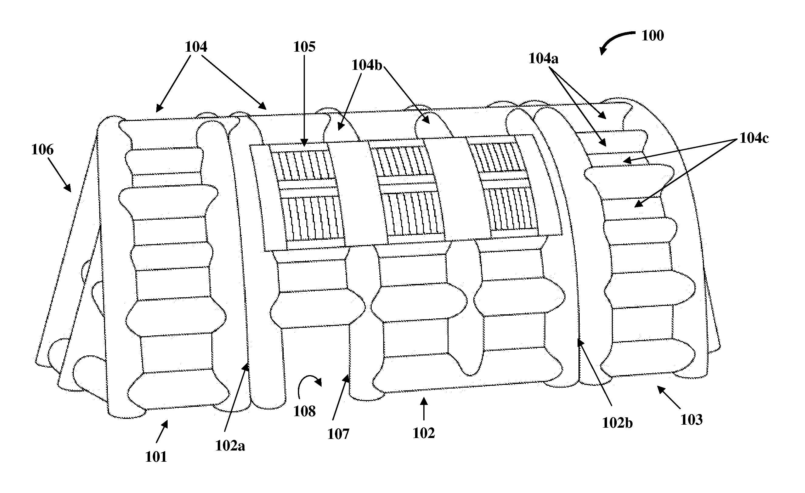
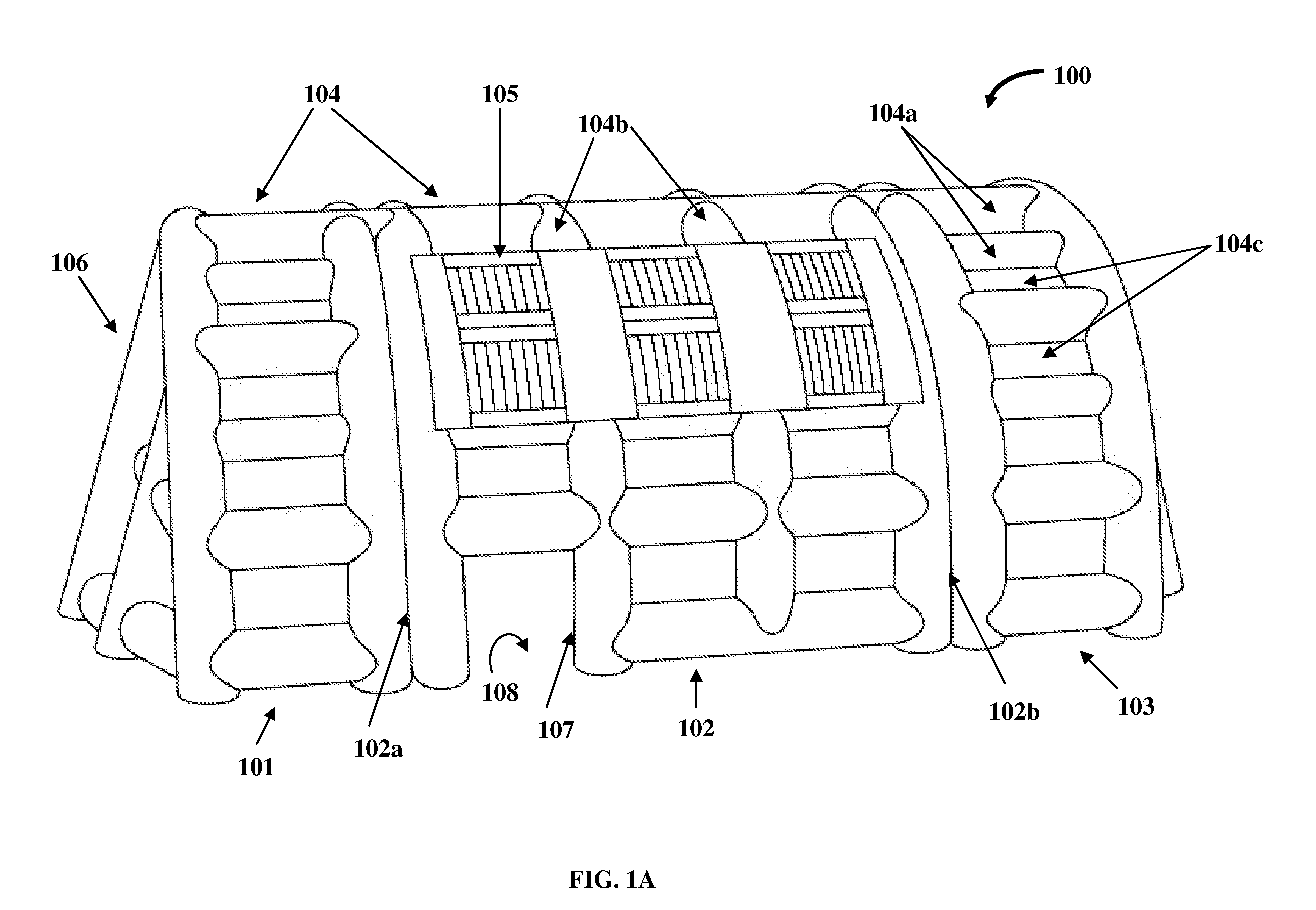
[0006]The inflatable enclosure disclosed herein further comprises multiple tile members the dimensions of which are configured to allow the tile members to be inserted in the openings in the inflatable structural framework of each of the inflatable middle section and the inflatable end sections and to plug and sealably encase the openings when the tile members are inflated in the inflatable structural framework. Each of the tile members defines an enclosed annular space for receiving a fluid, for example, air, to inflate each of the tile members. The enclosed annular space within each of the tile members is inflated prior to, or inflated after insertion of the tile members into the openings in the inflatable structural framework to plug and sealably encase the openings in the inflatable structural framework. The tile members when inflated contiguously secure the tile members with the pneumatically interconnected inflated beams in the inflatable structural framework, to provide multidimensional structural strength and stability to the inflatable structural framework and to minimize deformation of the inflatable structural framework under load.
[0007]Each of the tile members comprises an inflatable cell structure and an apron membrane. The apron membrane defines a periphery around the inflatable cell structure. The inflatable cell structure of each of the tile members comprises a multidimensional array of one or more inflatable air cells. The inflatable cell structure defines an enclosed annular space within each of the air cells of the inflatable cell structure for receiving a fluid, for example, air, to inflate the inflatable 
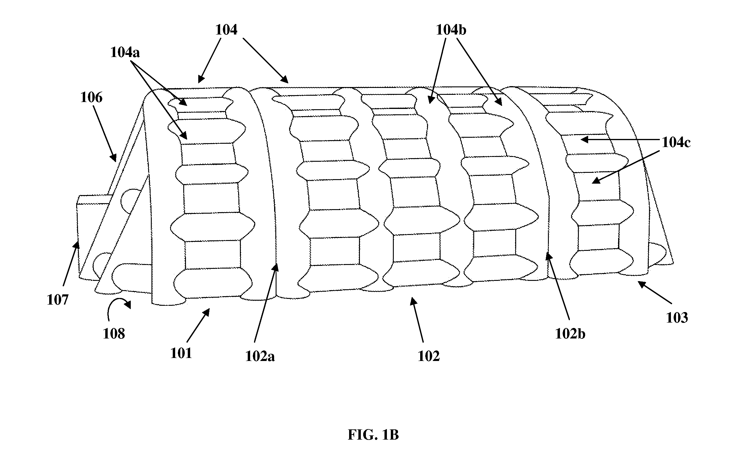
cell structure. The inflatable cell structure of each of the tile members is inserted in one or more of the openings in the inflatable structural framework to plug the openings. The enclosed annular space within each of the air cells of the inflatable cell structure of each of the tile members is inflated prior to insertion of the inflatable cell structure into the openings in the inflatable structural framework. In an embodiment, the inflatable cell structure of each of the tile members is inflated after insertion of the inflatable cell structure into the openings in the inflatable structural framework. The inflatable cell structure positioned within the openings of the inflatable structural framework provides multidimensional strength and stability to the inflatable structural framework, when inflated. In an embodiment, one or more of the tile members are opposably positioned within each of the openings in the inflatable structural framework to create an insulating weather seal for the inflatable enclosure.
[0008]In an embodiment, one or more pneumatic sensors are operably connected to one or more of the pneumatically interconnected inflated beams of the inflatable structural framework for monitoring internal air pressure of the inflatable structural framework of the inflatable enclosure. A pneumatic pump, in communication with the pneumatic sensors, maintains a constant internal air pressure within the inflatable structural framework of the inflatable enclosure. In another embodiment, an outer membranous sheath is provided for enclosing the inflatable enclosure and the tile members for providing a smooth weatherproof finish to the inflatable enclosure.
[0009]The weather resistant tile members securely inserted in the openings in the inflatable structural framework of the inflatable enclosure enable versatility of the inflatable enclosure for different weather conditions. Other advantages of the inflatable enclosure disclosed herein comprise, for example, rapid deployment, aerodynamically designed shape and structure for wind sheer, low opacity of the tile members to allow natural light inside the inflatable enclosure, etc.

Problems solved by technology

Conventional inflatable shelters utilize complex rigid or inflatable support structures that are difficult to manufacture.
Another drawback of conventional inflatable shelters is that the support structures used for these shelters are only suitable for building shelters having smaller dimensions due to load constraints.
When larger shelters having inflatable support structures are erected, the inflatable support structures may wrinkle, buckle and even collapse under snow or high wind loads.
Current rigid or inflatable systems do not address the need for a relatively larger pneumatically inflatable structure that can withstand and support heavy loads, and that may be readily transportable in that, when collapsed or deflated, the structure is not exceedingly heavy or overly bulky.
Hence, there is a long felt but unresolved need for an inflatable enclosure that can be easily erected to provide a shelter for different applications that require small to large shelter spans, and that provides a weather seal under outdoor conditions.

Method used


Image

  • Inflatable Enclosure
  • Inflatable Enclosure
  • Inflatable Enclosure

Examples


Embodiment Construction

[0024]FIGS. 1A-1B exemplarily illustrate perspective views of an inflatable enclosure 100. The inflatable enclosure 100 disclosed herein is a temporary airframe enclosure erected on a ground surface 108 for different applications and activities such as living, entertainment, sports, manufacturing, storage, recreation, etc. As exemplarily illustrated in FIGS. 1A-1B, the inflatable enclosure 100 comprises an inflatable middle section 102 and one or more inflatable end sections 101 and 103 abutting opposing ends 102a and 102b of the inflatable middle section 102 to enclose a space 401 for which the inflatable enclosure 100 is designed for, for example, a sports court, an exhibition, etc., as exemplarily illustrated in FIG. 4. The inflatable middle section 102 is generally arcuate in shape. Each of the inflatable middle section 102 and the inflatable end sections 101 and 103 comprises an inflatable structural framework 104. The inflatable structural framework 104 comprises a network of ...


PUM


Abstract

An inflatable enclosure and a method for erecting the inflatable enclosure are provided. The inflatable enclosure comprises an inflatable middle section and inflatable end sections abutting opposing ends of the inflatable middle section to enclose a space. Each of the inflatable middle section and the inflatable end sections comprises an inflatable structural framework. The inflatable structural framework comprises a network of pneumatically interconnected inflated beams that defines one or more openings of predetermined shapes in the inflatable structural framework. The inflatable enclosure comprises multiple tile members that are inserted in the openings in the inflatable structural framework. The tile members are configured to plug and sealably encase the openings to form a contiguous structure with the pneumatically interconnected inflated beams, when inflated. The inflatable middle section and the inflatable end sections are inflated, assembled, and anchored to a ground surface for spanning a predefined area on the ground surface.

Description

BACKGROUND[0001]Inflatable shelters, in general, provide temporary enclosures for indoor and outdoor sports, construction sites, commercial storage, and recreational purposes. Conventional inflatable shelters utilize complex rigid or inflatable support structures that are difficult to manufacture. For example, conventional inflatable shelters comprise fiberglass poles for support structures, which when bent into an arch provide a supporting framework for the exterior fabric skin or canopy of the shelter. Furthermore, conventional inflatable shelters are generally manufactured and assembled in such a way that once damaged, the entire shelter must be replaced. Another drawback of conventional inflatable shelters is that the support structures used for these shelters are only suitable for building shelters having smaller dimensions due to load constraints. The shelters may be erected as small units not larger than about 20 meters in width or diameter. When larger shelters having inflat...

Claims


Application Information

Patent Timeline
Patent Type & Authority Applications(United States)
IPC IPC(8): E04H15/20E04B1/00
CPCE04H15/20E04H2015/207E04H2015/206E04H2015/201
Inventor ROSS-DA SILVA, CHRISTOPHER
Owner SMART ENCLOSURE
Why Eureka
Try Eureka