
Aircraft actuator hydraulic system

a technology of hydraulic system and actuator, which is applied in the direction of fluid coupling, coupling, transportation and packaging, etc., can solve the problems of reducing the efficiency of the aircraft body, reducing the size of the actuator, and reducing the aerodynamic drag sufficiently, so as to achieve the effect of low cos

Active Publication Date: 2012-05-31
NABLESCO CORP
View PDF17 Cites 17 Cited by
  • Summary
  • Abstract
  • Description
  • Claims
  • Application Information

AI Technical Summary

Benefits of technology

[0010]In view of the foregoing circumstances, it is an object of the present invention to provide an aircraft actuator hydraulic system that includes a plurality of actuators for driving the same control surface, in which the control surface can be driven by a single actuator even in the case of a loss or degradation in the function of an aircraft central hydraulic power source, a size reduction can be realized for a high-output actuator at a low cost, and the actuators can be installed inside a thinned wing.
[0012]With this configuration, the aircraft actuator hydraulic system is provided as a hydraulic system including a plurality of actuators, namely, first and second actuators for driving the same control surface. Also, with this hydraulic system, even if a loss or degradation occurs in the function of the first and second aircraft central hydraulic power sources, the control surface can be driven by a single actuator, namely, the first actuator to which the pressure oil is supplied from the backup hydraulic pump installed inside the wing and therefore it is possible to ensure high reliability.
[0013]Further, the backup hydraulic pump is set such that its maximum discharge pressure is greater than the maximum discharge pressures of the first aircraft central hydraulic pump and the second aircraft central hydraulic pump. Accordingly, the backup hydraulic pump, rather than the first and second aircraft central hydraulic pumps, can be adapted to high pressure, thus making it possible to achieve a high output in the first actuator even with a small pressure receiving area. Accordingly, it is possible to reduce the size of the high-output first actuator. Note that the first actuator is configured such that the control surface can be driven by a single actuator, namely, the actuator with the pressure oil supplied from the backup hydraulic pump. Therefore, the second actuator does not need to be adapted to a high output in the same manner as the first actuator, and therefore its size can be reduced. Further, since the backup hydraulic pump installed inside the wing can be adapted to high pressure without adapting the first and second aircraft central hydraulic pumps to high pressure, it is not necessary to adapt the entire hydraulic system from the aircraft central hydraulic power sources to the actuators to high pressure. Accordingly, it is possible to realize a size reduction for the high-output first actuator at a low cost. Further, since it is possible to realize a size reduction for the high-output first actuator and a size reduction for the second actuator, it is possible to install the first and second actuators inside the wing having a reduced thickness.
[0014]Therefore, with this configuration, in an aircraft actuator hydraulic system including a plurality of actuators for driving the same control surface, the control surface can be driven by a single actuator, even in the case of a loss or degradation in the function of the aircraft central hydraulic power sources, and it is possible to realize a size reduction for the high-output actuator at a low cost and install the actuators inside the wing having a reduced thickness.

Problems solved by technology

Therefore, there are severe constraints on reducing the size of the actuators.
In this case, even if a fairing for covering the surface of the actuator is provided for reducing the aerodynamic drag, it is difficult to sufficiently reduce the aerodynamic drag, resulting in a reduced efficiency of the aircraft body.
This leads to a significant cost increase due to, for example, the fact that a special material that can be adapted to high pressure needs to be used for the entire hydraulic system.

Method used


Image

  • Aircraft actuator hydraulic system
  • Aircraft actuator hydraulic system
  • Aircraft actuator hydraulic system

Examples


Embodiment Construction

[0021]Hereinafter, an embodiment for carrying out the present invention will be described with reference to the accompanying drawings. It should be appreciated that an embodiment of the present invention can be widely applied as an aircraft actuator hydraulic system that includes hydraulically operated actuators for driving a control surface of an aircraft and that supplies pressure oil to the actuators.

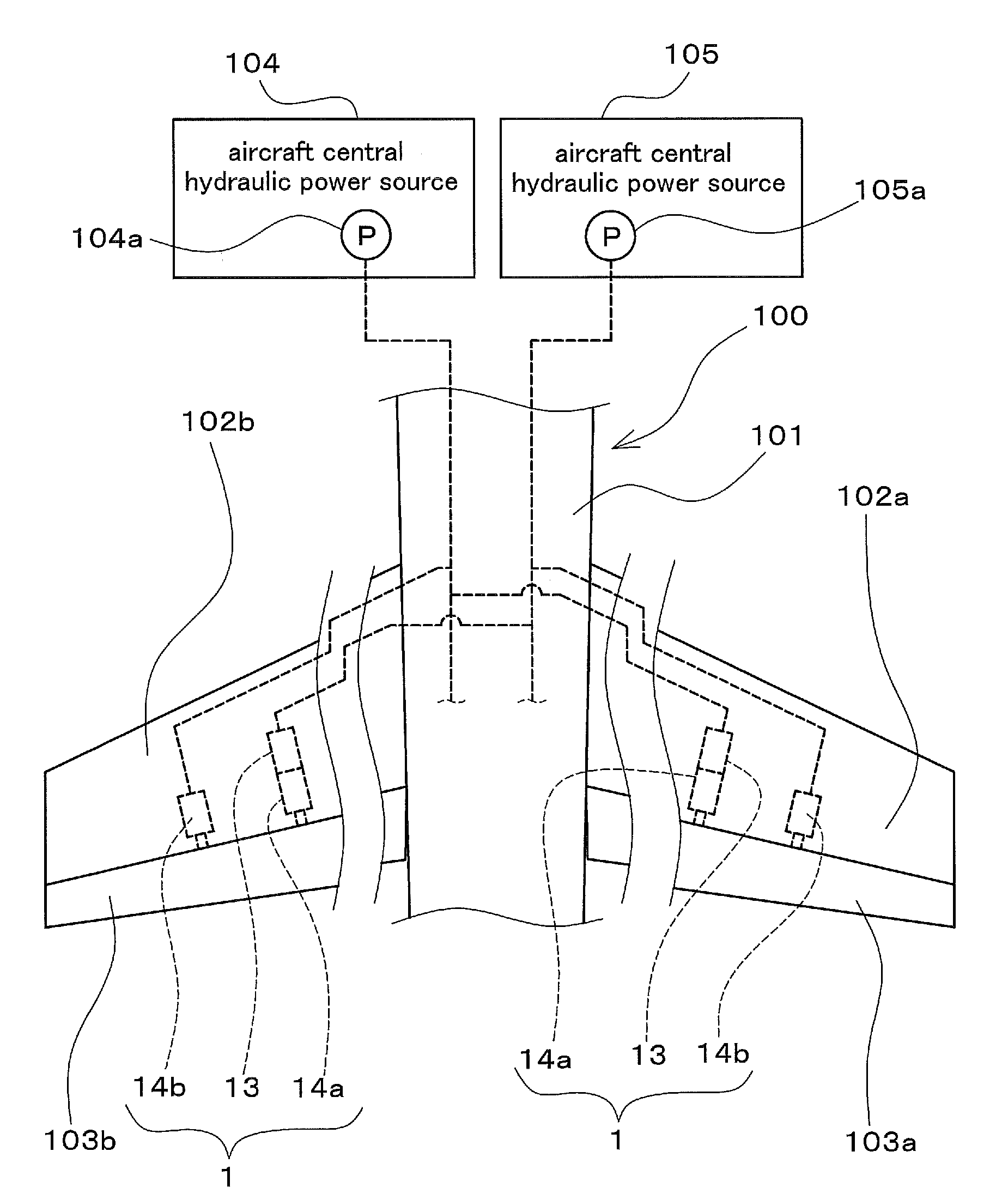
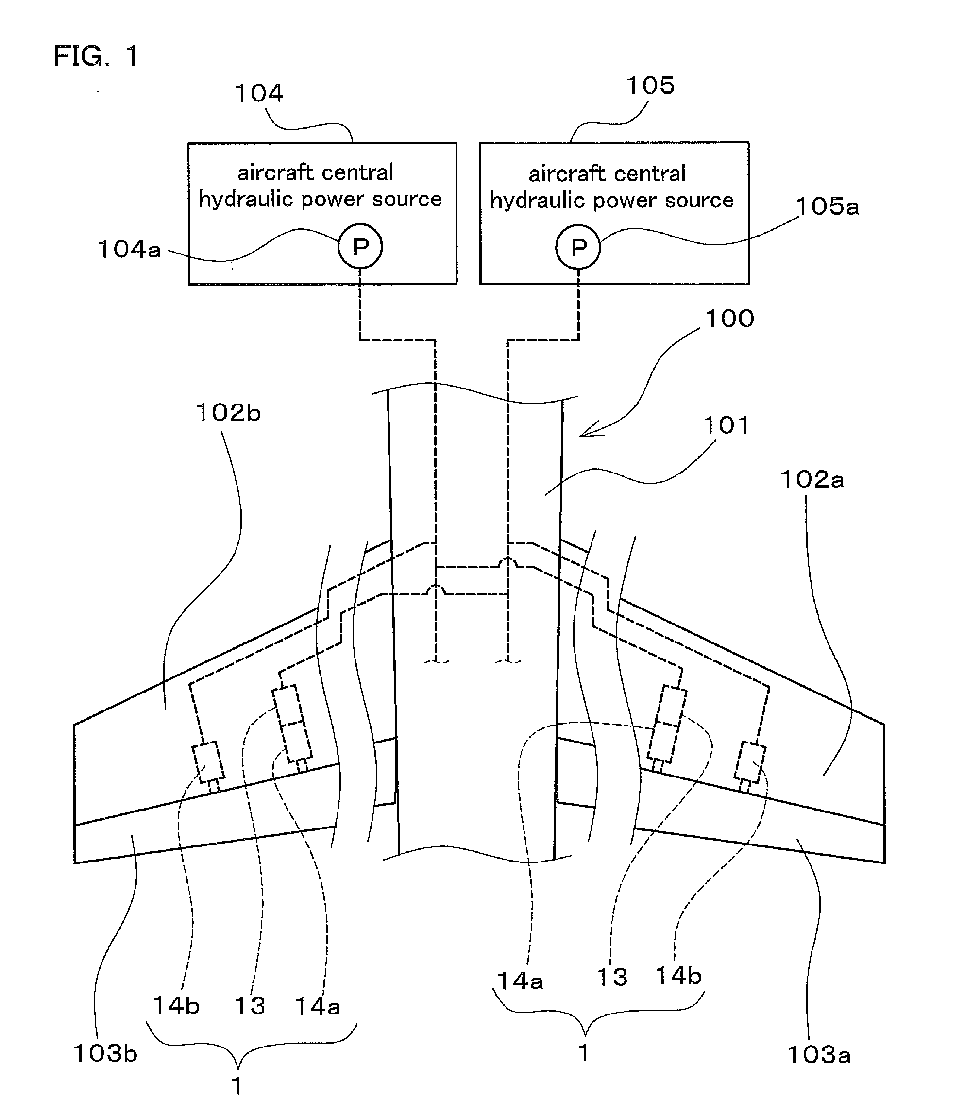
[0022]FIG. 1 is a diagram schematically showing part of an aircraft 100 to which an aircraft actuator hydraulic system 1 (hereinafter, also simply referred to as a “hydraulic system 1”) according to an embodiment of the present invention is applied, showing part of a fuselage portion of a body 101 of the aircraft 100 and a pair of main wings (102a, 102b). In FIG. 1, the illustration of the intermediate portions of the main wings (102a, 102b) is omitted.

[0023]The main wing 102a is provided with an aileron 103a as a moving surface (flight control surface) constituting a control surface...


PUM


Abstract

A first actuator drives a control surface by being operated by supply of pressure oil from a first aircraft central hydraulic power source including a first aircraft central hydraulic pump. A second actuator drives the control surface by being operated by supply of pressure oil from a second aircraft central hydraulic power source including a second aircraft central hydraulic pump. A backup hydraulic pump is installed inside a wing of the aircraft and is provided so as to be able to supply pressure oil to the first actuator when a loss or degradation in a function of at least one of the first aircraft central hydraulic power source and the second aircraft central hydraulic power source occurs. A maximum discharge pressure of the backup hydraulic pump is set to be greater than maximum discharge pressures of the first aircraft central hydraulic pump and the second aircraft central hydraulic pump.

Description

BACKGROUND OF THE INVENTION[0001]1. Field of the Invention[0002]The present invention relates to an aircraft actuator hydraulic system that includes hydraulically operated actuators for driving a control surface of an aircraft and that supplies pressure oil to the actuators.[0003]2. Description of Related Art[0004]An aircraft is provided with control surfaces that are formed as moving surfaces (flight control surfaces) and are configured as an aileron, an elevator, a rudder, and the like. Hydraulically operated actuators are often used as actuators for driving such control surfaces. Note that, as disclosed in JP 2003-040199A, in an aircraft, for example, two hydraulically operated actuators are attached to one control surface and the control surface is driven by these two actuators.[0005]Pressure oil is supplied to an actuator such as the above from an aircraft central hydraulic power source. Also, pressure oil is supplied to two actuators from separate aircraft central hydraulic po...

Claims


Application Information

Patent Timeline
Patent Type & Authority Applications(United States)
IPC IPC(8): F16D31/02
CPCB64C13/42F15B2211/20592F15B2211/30505F15B2211/50536F15B2211/8757F15B2211/6313F15B2211/6336F15B2211/6651F15B2211/7107F15B2211/5753
Inventor FUKUI, ATSUSHITAKAGI, NORIMASA
Owner NABLESCO CORP
Learn More