Dry Carbon Dioxide Capture Apparatus

a carbon dioxide and capture apparatus technology, applied in the direction of chemistry apparatus and processes, separation processes, dispersed particle separation, etc., can solve the problems of limited co2 /sub>separation efficiency and process demerit of further creating waste water, and achieve the effect of enhancing the efficiency of co2 captur

Active Publication Date: 2012-05-31
KOREA INST OF ENERGY RES
View PDF7 Cites 5 Cited by
  • Summary
  • Abstract
  • Description
  • Claims
  • Application Information

AI Technical Summary

Benefits of technology

[0011]Therefore, the present invention has been proposed to solve the above problems in the related art and is directed to provision of a dry CO2 capture apparatus having a bubble flow capture device and capable of preventing a gas backflow toward a vertical transport line, to thereby improve CO2 capture efficiency.
[0019]According to the present invention, there is provided a dry CO2 capture apparatus, including: a bubble flow capture device adopted as an adsorption reactor of the dry CO2 capture apparatus for treating exhaust gas in a large quantity, rather than the existing high speed fluidization column; and a vertical riser provided in an adsorption column to prevent a gas backflow, thus enhancing CO2 capture removal efficiency.

Problems solved by technology

However, the wet process has a demerit of further creating waste water during operation of the wet process.
Accordingly, due to differences in CO2 and H2O concentrations in the recovery reactor, the CO2 separation efficiency is limited.

Method used


Image

  • Dry Carbon Dioxide Capture Apparatus
  • Dry Carbon Dioxide Capture Apparatus
  • Dry Carbon Dioxide Capture Apparatus

Examples


Embodiment Construction

[0023]The present invention will now be described more fully hereinafter with reference to the accompanying drawings forming a part of this specification wherein like reference characters designate corresponding parts in the several views. In the embodiments of the present invention, detailed description of the publicly known functions and configurations that are judged to be able to make the purport of the present invention unnecessarily obscure are omitted.

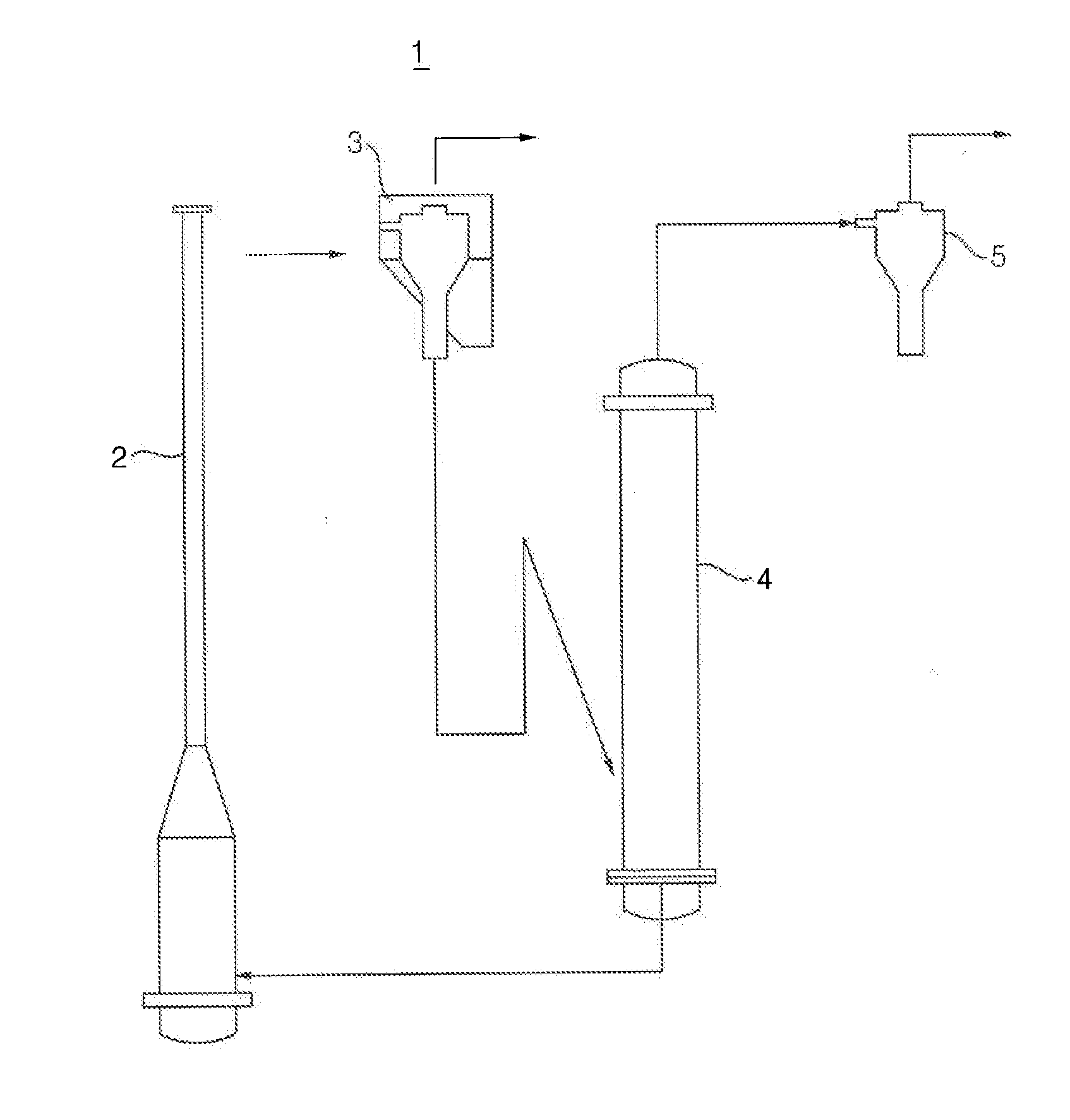
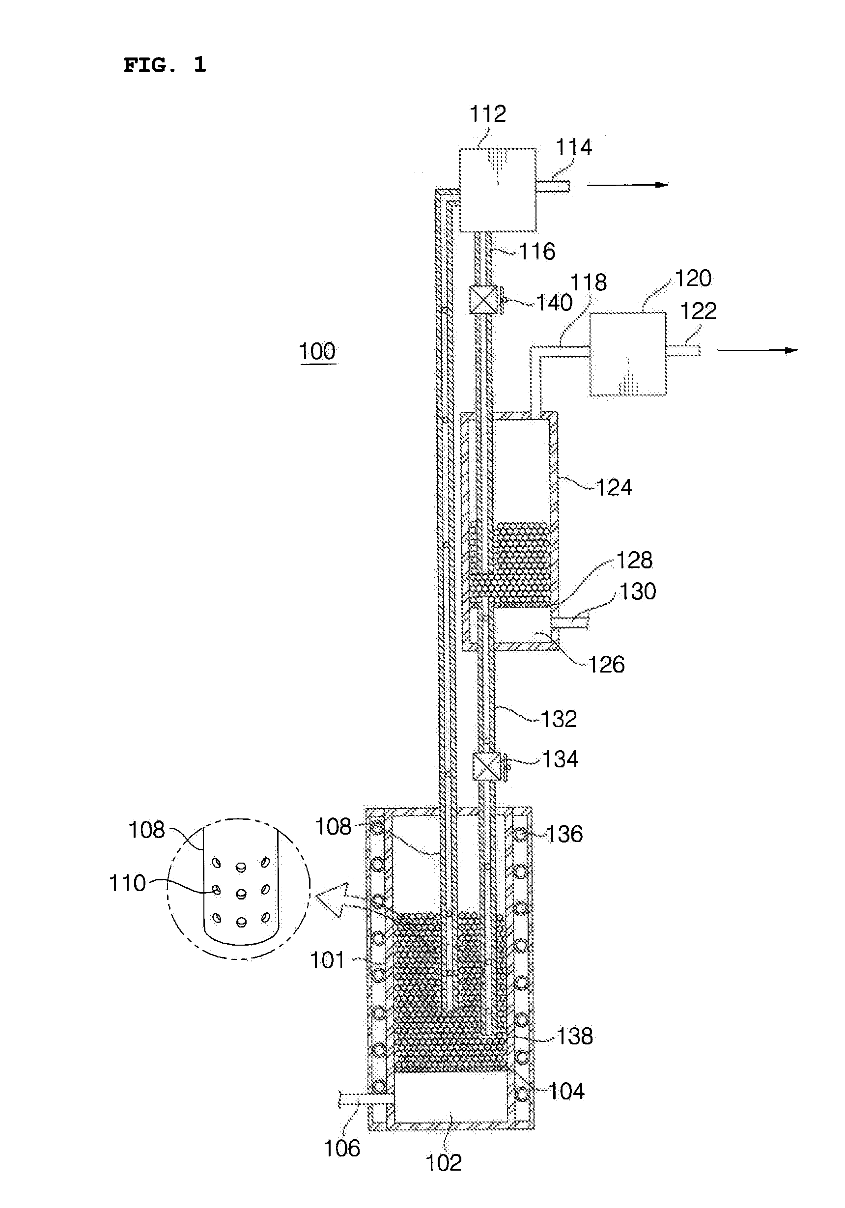
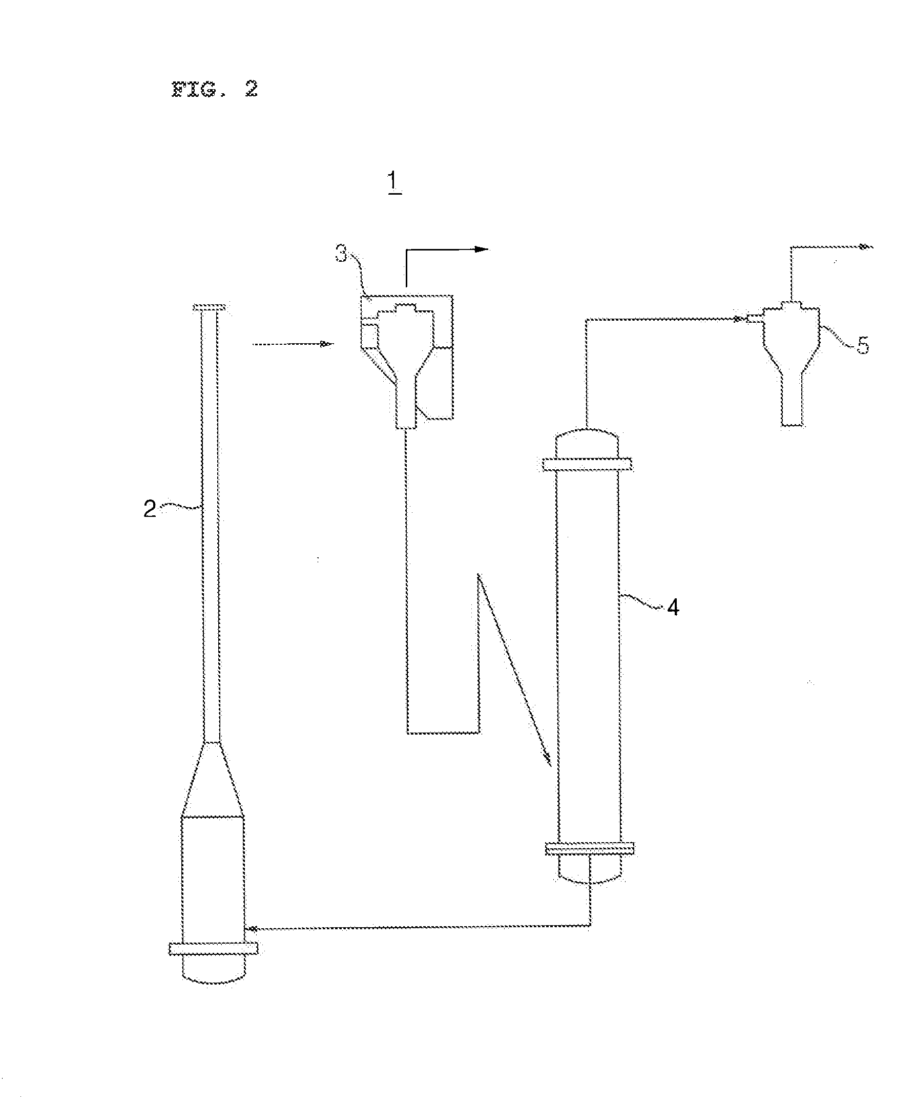
[0024]Referring to FIG. 1, reference numeral 100 denotes a dry CO2 capture apparatus. The dry CO2 capture apparatus 100 generally includes a capture reactor 101 and a regenerator 124. A first separator 112 is provided in front of the regenerator 124 while a second separator 120 is located at the rear side of the regenerator 124, in order to separate CO2 and a gas residue free from CO2, respectively.

[0025]The capture reactor 101 is a sealed chamber having a space in which reaction is conducted. Bottom side of the capture reactor ...


PUM

PropertyMeasurementUnit
heightaaaaaaaaaa
adsorptionaaaaaaaaaa
concentrationsaaaaaaaaaa

Abstract

Disclosed is a dry carbon dioxide capture apparatus with improved carbon dioxide capture efficiency through preventing gas backflows into vertical transport lines. The dry CO2 capture apparatus includes a capture reactor having a capture buffer chamber on the bottom side, a capture diffusion plate on top of the capture buffer chamber, and adsorbent particles in a space above the capture diffusion plate; a first separator connected to the capture reactor through a vertical transport line; a regenerator having a regeneration buffer chamber on the bottom side, a regenerating diffusion plate on top of the regeneration buffer chamber, and adsorbent particles in a space above the regenerating diffusion plate; a second separator connected to the regenerator through a gas separation line; and a second particle transfer line connected to the regenerator at one end and connected to the capture reactor at the other end.

Description

CROSS REFERENCE TO RELATED APPLICATIONS[0001]This application claims priority from Korean Patent Application No. 10-2010-0120741, filed on Nov. 30, 2010 in the Korean Intellectual Property Office, the entire disclosure of which is incorporated herein by reference.BACKGROUND OF THE INVENTION[0002]1. Field of the Invention[0003]The present invention relates to a dry carbon dioxide capture apparatus and, more particularly, to a dry carbon dioxide capture apparatus enabling improvement in carbon dioxide capture efficiency by preventing a gas backflow into a vertical transport line.[0004]2. Background Art[0005]A carbon dioxide capture apparatus in related art generally employs a wet process to recover CO2. Treat is, the wet process is carried out by passing CO2-containing gas through an amine solution, to allow CO2 to be absorbed into the solution and regenerating the solution in a regeneration column, thus reusing the solution. However, the wet process has a demerit of further creating ...

Claims


Application Information

Patent Timeline
Patent Type & Authority Applications(United States)
IPC IPC(8): B01D53/02
CPCB01D53/10B01D53/60B01D53/62Y02C10/08B01D2253/102Y02C10/04Y02C10/06B01D53/83Y02A50/20Y02C20/40
Inventor YI, CHANG-KEUNJIN, GYONG-TAESUN, DO-WONJO, SUNG-HOPARK, JAE-HYEONBAE, DAL-HEERYU, HO-JUNGPARK, YOUNG-CHEOLLEE, SEUNG-YONGMOON, JONG-HO
Owner KOREA INST OF ENERGY RES
Why Eureka
Try Eureka