Absorbent regeneration with flashed lean solution and heat integration

a technology of absorbent regeneration and flashed lean solution, which is applied in the field of co2 capture from a gas mixture, can solve the problems of reduced efficiency compared with a traditional plant, reduced efficiency, and less profit for facilities, and achieves the effect of reducing the duty of reboilers and reducing the demand

Inactive Publication Date: 2010-03-11
AKER CLEAN CARBON
View PDF5 Cites 30 Cited by
  • Summary
  • Abstract
  • Description
  • Claims
  • Application Information

AI Technical Summary

Benefits of technology

[0018]wherein the lean absorbent leaving the regenerator column is flashed to produce a gaseous phase that is compressed and reintroduced into the regeneration column, and a liquid phase that is heat exchanged against the rich absorbent. The combination of flashing of the lean absorbent leaving the regenerator, compressing the gaseous phase, introduction of the compressed gaseous phase into the regenerator as steam for stripping of absorbent, and further cooling the liquid phase after flashing against the rich absorbent before introduction into the regenerator, reduces the heat loss in the regenerator by recycling more of the heat energy back to the regenerator. Additionally, the liquid phase after flashing, or the lean absorbent to be returned to the absorber, is additionally cooled, which is advantageous for the absorption process. The combination also enables better use of low temperature heat. The combined effect of this process design is that the temperature profile in the column is improved and that heat normally transferred from lean amine to rich amine is maintained at the base of the stripper. The total result is an improved efficiency of the capturing process and an improved energy balance of the system.
[0019]According to a first embodiment of the first aspect, the compressed gaseous phase is mixed with water to cool and saturate the gaseous phase with steam before introduction into the regeneration column. After compression the gaseous phase normally has a temperature higher than required for introduction into the regeneration column. Introduction of water into the steam both cools the gas and saturates the steam with water to improve the utility of the compressed gaseous phase for regenerating the absorbent.
[0026]According to a third aspect the present invention provides for a regenerator for a liquid absorbent for CO2 comprising a regeneration column, a rich absorbent line for introduction of rich absorbent into the regeneration column, withdrawal means for withdrawing lean adsorbent from the bottom of the regeneration column, a reboiler for heating of a portion of the withdrawn absorbent before reintroduction into the regeneration column for production of steam that is reintroduced into the column, a lean absorbent line for recycling of a portion of the absorbent withdrawn by withdrawal means to an absorber, a heat exchanger for heating rich absorbent against the withdrawn lean absorbent and a heat exchanger to additionally heat the heated rich absorbent against a low temperature heat source before the rich gas enters the regenerator, a gas withdrawal line for withdrawal of CO2 and vapor from the top of the regeneration column, and separation means for separating the gas withdrawn from the top of the regeneration column in a CO2 stream that is exported from the regenerator, and water that is recycled to the regeneration column, the regenerator further comprises flashing means, a steam withdrawal line connecting said flashing means with a compressor for compression of a withdrawn gaseous phase, a line for injecting the compressed gaseous phase into the regeneration column, and a lean absorbent line connecting the flashing means with the heat exchanger. The combination of flashing means, a compressor for compressing the gaseous phase after flashing, an injection line for injection the compressed gaseous phase into the regenerator, and the lean absorption line for the liquid phase, or lean absorbent line introducing the lean absorbent into the heat exchanger for further cooling of the lean absorbent, and heating of the rich absorbent, results in an improved efficiency of the process and in lower heat loss than for regeneration plants according to the prior art.

Problems solved by technology

The plants for capturing of CO2 are relative large, complex and expensive constructions.
The reduced efficiency compared with a traditional plant makes these facilities less profitable.
The heat loss in the absorption and regeneration cycle of the CO2 capturing process, is, however, still too high and improved plants and methods are still sought.

Method used


Image

  • Absorbent regeneration with flashed lean solution and heat integration
  • Absorbent regeneration with flashed lean solution and heat integration
  • Absorbent regeneration with flashed lean solution and heat integration

Examples


Embodiment Construction

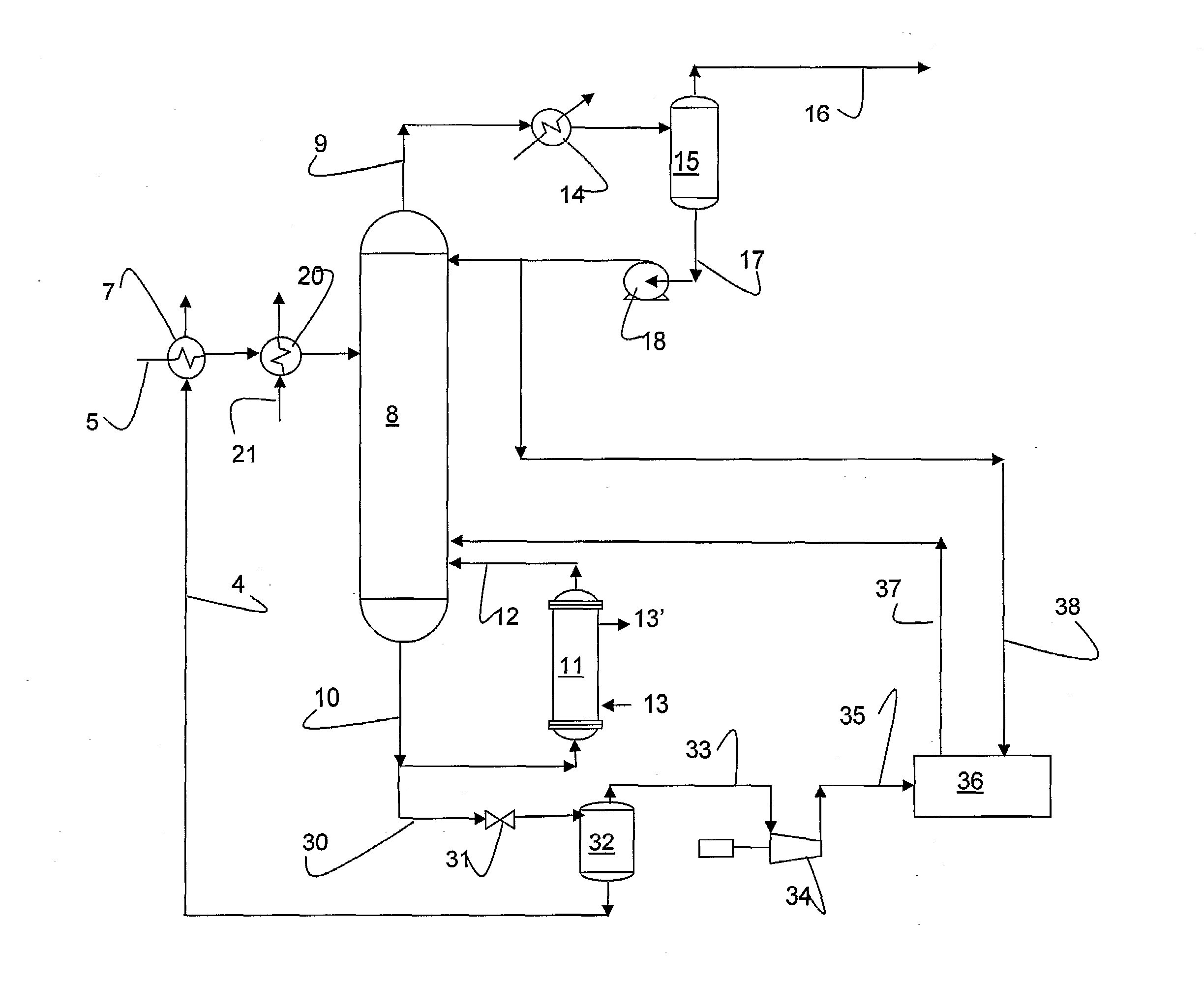
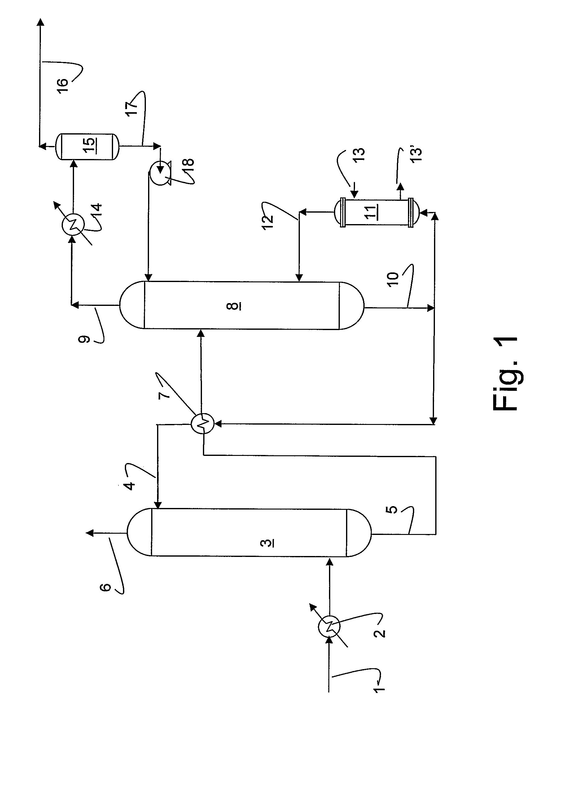
[0038]FIG. 1 illustrates a CO2 capturing plant according to the prior art, where exhaust gas from combustion of carbonaceous fuel enters the CO2 capturing plant through an exhaust line 1. The exhaust gas in line 1 is substantially cooled by utilization of the high temperature heat energy from the combustion for production of electrical energy. The temperature of the exhaust entering the CO2 capturing plant through line is normally from about 120° C. to about 90° C. The exhaust gas from line 1 is optionally introduced into a cooling section in which it is saturated with water and cooled to a temperature e.g. from about 35° C. to about 60° C.

[0039]The cooled and humidified exhaust gas is then introduced into the lower part of an absorption tower 3 in which the exhaust gas flows from the bottom to the top of the absorption tower 3 countercurrent to a lean absorbent, i.e. absorbent that is stripped for CO2, that is introduced into the upper part of the absorption tower through a lean ab...


PUM

PropertyMeasurementUnit
inlet temperatureaaaaaaaaaa
temperatureaaaaaaaaaa

Abstract

A method for regeneration of a rich absorbent having absorbed CO2 (5) to give a regenerated, or lean absorbent (4) wherein the lean absorbent leaving the regenerator column is flashed (32) to produce a gaseous phase (33) that is compressed (34) and reintroduced into the regeneration column, and a liquid lean absorbent phase (4) that is heat exchanged (7) against the rich absorbent.

Description

TECHNICAL FIELD [0001]The present invention relates to the field of CO2 capture from a gas mixture. More specifically the present invention relates to CO2 capture from a CO2 containing gas, such as combustion gas from combustion of carbonaceous material or from other CO2 liberating processes. Most specifically the present invention relates to an improved method and plant for regeneration of a CO2 absorbent in a method and plant for capturing of CO2.BACKGROUND [0002]The continually increasing combustion of fossil fuel, such as coal, natural gas and oil, during the last centuries has resulted in an increase in the concentration of CO2 in the atmosphere. The increasing concentration of CO2 has caused concern due to the greenhouse effect caused by CO2. The greenhouse effect is suspected already to have caused at least some of the changes in the climate that have been seen during the last decades, and is according to simulation models suspected to cause even more and potentially dramatic...

Claims


Application Information

Patent Timeline
Patent Type & Authority Applications(United States)
IPC IPC(8): B01J20/34C01B31/20B01D19/00C01B32/50
CPCB01D53/1425Y02C10/06C01B31/20B01D53/1475C01B32/50Y02P20/151Y02C20/40
Inventor WOODHOUSE, SIMONRUSHFELDT, PAL
Owner AKER CLEAN CARBON
Why Eureka
Try Eureka