Airborne material collection and detection method and apparatus

a detection method and airborne technology, applied in chemical methods analysis, laboratory glassware, instruments, etc., can solve the problems of ineffective capture of hazardous contaminants, gas or mist, other materials of low inertia, and inability to efficiently collect materials, etc., to achieve efficient communication with central locations

Inactive Publication Date: 2007-09-27
DING ZHONG
View PDF8 Cites 30 Cited by
  • Summary
  • Abstract
  • Description
  • Claims
  • Application Information

AI Technical Summary

Benefits of technology

[0039] In performing the analysis of collected drops by the apparatus of the present invention, the various optical, pressure, and electrical signals may be sent to a signal processing computer to perform the detection and analysis. Instructions may be sent out to control the fluid movement, temperature, optical intensity, and other parameters within the apparatus, or an alarm may be sounded if a hazardous contaminant is detected. In a further embodiment, a computer network may be provided to efficiently communicate with central locations for signal analysis, decision making, or alarming.

Problems solved by technology

A major disadvantage of this method is that only higher density hazardous contaminants can be effectively trapped, and other materials of low inertia, such as toxic gas or mist, can not be efficiently collected.
Another disadvantage of this method is that hazardous contaminants can bounce in the impactor devices without collection.
Again, lower density airborne hazardous contaminants can not be effectively collected, and hazardous contaminants can still deposit on various surfaces of virtual impactor structures, especially at curved portions.
The big disadvantage of such two stage sample collections and analyses is that they are inefficient and it is impossible to perform detection in real time, i.e. a time frame on the order of a few minutes.
During this time period, the concentration of such hazardous materials has reached a toxic level for a sufficient period of time such that harm has occurred to humans and other species of life that are present—i.e.
“the damage has already been done.” In addition, to attempt to adapt such systems to perform continuous collection, wash, and analysis of an air stream would likely require a system that is too high in cost.
One of the disadvantages of this method is that particulate in the collector and fan can not be rinsed efficiently by the liquid.
Another disadvantage is that smaller particulate, especially those of gaseous phase or aerogel, can not be collected by the impact collector and the fan.
Yet another disadvantage is the uncertainty of when to rinse.
Otherwise, if the time interval for rinse and analysis is too large, the airborne hazardous contaminant may have already created environmental damage, or have had an adverse effect on humans and / or other species in the environment before analysis is performed.
One disadvantage of this type of method is that a large volume of liquid is required for the analysis.
Yet another disadvantage of the method is that it works only when a human operator initiates it based upon his judgment of a situation.
The apparatus used in such method cannot be mounted on a wall to collect and monitor the airborne hazardous contaminants continuously for a long period of time due to significant evaporation of the liquid thin film created in the apparatus.

Method used


Image

  • Airborne material collection and detection method and apparatus
  • Airborne material collection and detection method and apparatus
  • Airborne material collection and detection method and apparatus

Examples


Embodiment Construction

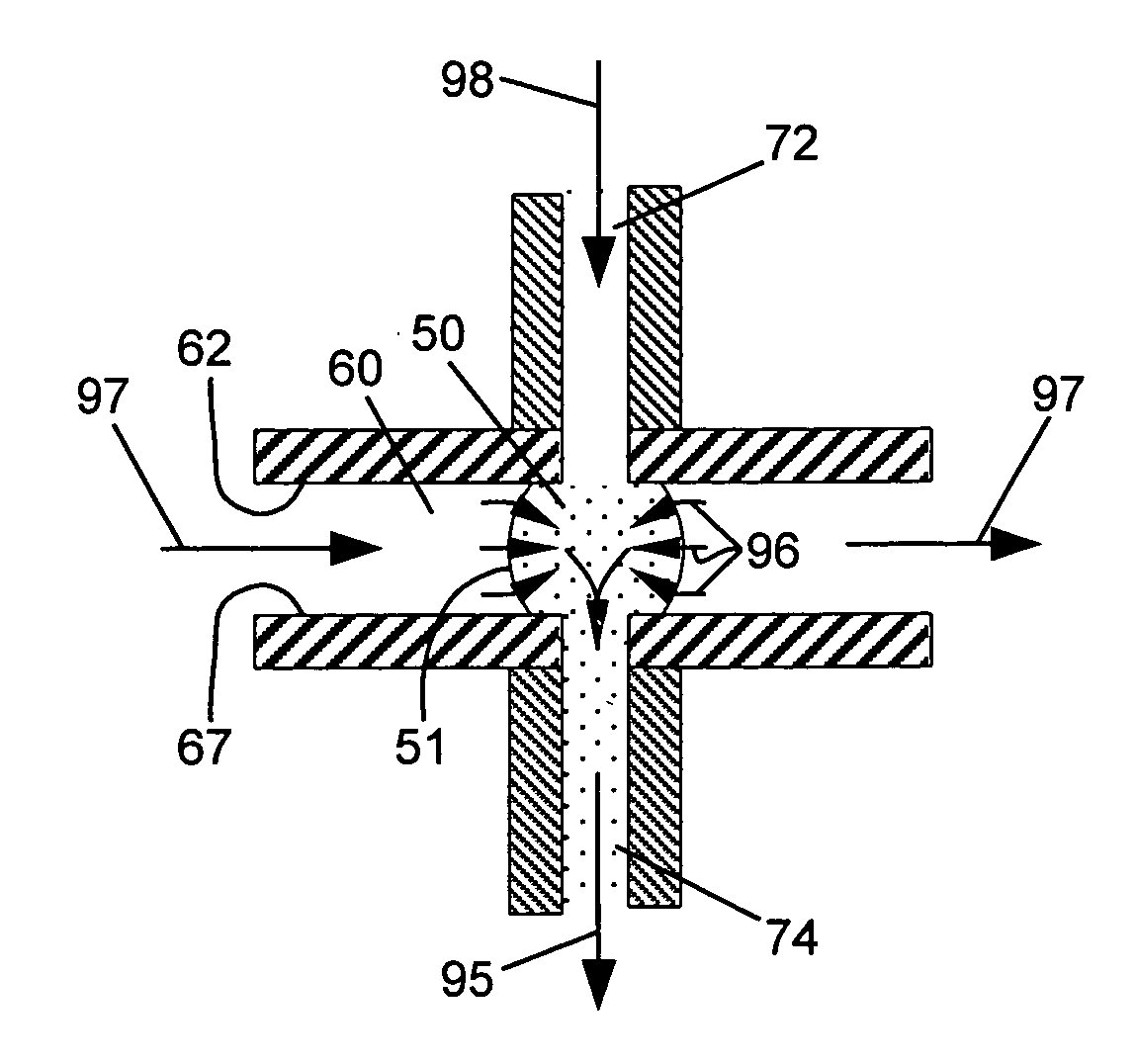
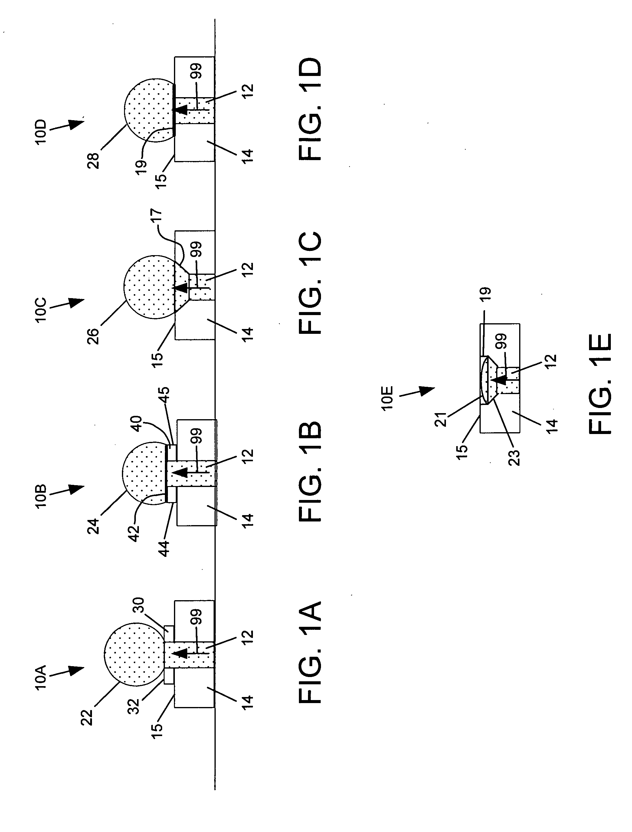
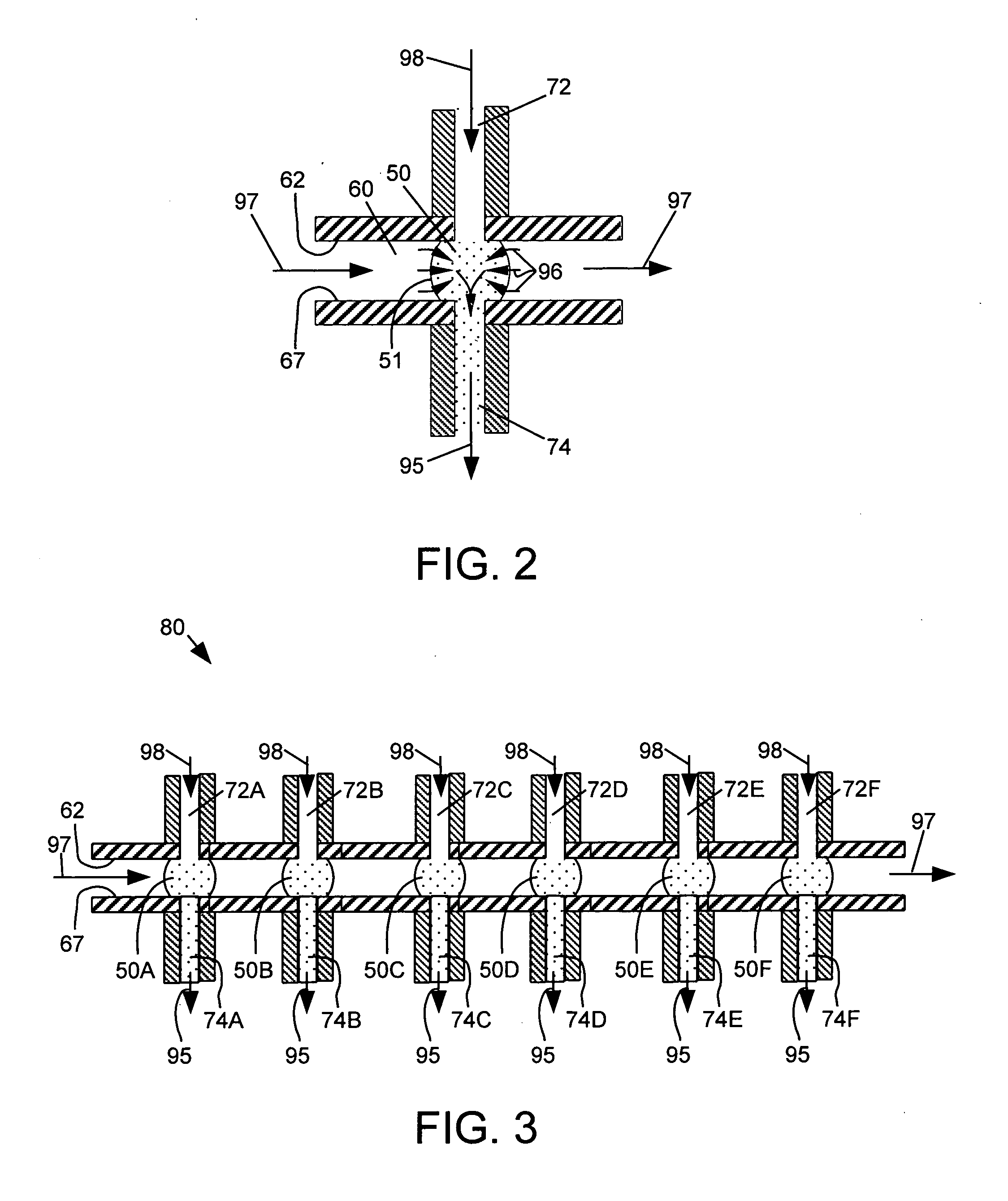
[0064] For a general understanding of the present invention, reference is made to the drawings. In the drawings, like reference numerals have been used throughout to designate identical elements.

[0065] As used herein, the term “hazardous contaminant” is meant to indicate a substance that has an adverse effect on another entity in the environment in which the substance is present. In particular, the adverse effect may be direct short-term or long term harm to the health of a human or other life form. The adverse effect may be the pollution of another material used by the human or other life form, e.g. drinking water. The adverse effect on a non-living entity may be a degradative effect, for example, the corrosion of a metal. In this specification, the terms “hazardous contaminant” and “contaminant” are used interchangeably, with the latter being used for the sake of brevity.

[0066] It is to be understood that in the description of the present invention in this specification and draw...


PUM

PropertyMeasurementUnit
diameteraaaaaaaaaa
diameteraaaaaaaaaa
diametersaaaaaaaaaa

Abstract

An apparatus and methods for airborne or gas borne chemical and biological sample collection and detection in real time using optical or chemical techniques, the apparatus comprising a chamber for delivery of said flowing gas stream containing a substance, the chamber comprising a first wall including a first wall surface and a longitudinal inlet channel disposed within the first wall and terminating at an outlet edge at the first wall surface; a second wall including a second wall surface and a longitudinal outlet channel disposed within the second wall and beginning at an outlet edge at the second wall surface, the longitudinal inlet channel aligned with the longitudinal outlet channel, and the first wall surface separated from the second wall surface by a gap; wherein the longitudinal inlet channel the longitudinal outlet channel are adapted for delivering a liquid into the inlet channel, through the chamber, and out the outlet channel such that a gas-liquid interface may be formed in the gap of the chamber.

Description

CROSS-REFERENCE TO RELATED PATENT APPLICATIONS [0001] This application claims the benefit of the filing date of U.S. provisional patent application Ser. No. 60 / 586,203 filed Jul. 8, 2004, and U.S. provisional patent application Ser. No. 60 / 663,963 filed Mar. 21, 2005, the disclosures of which are incorporated herein by reference.[0002] The invention relates to the collection and analysis of airborne hazardous contaminants, and more specifically to airborne chemical and biological sample collection and detection in real time with optical or chemical means. BACKGROUND OF THE INVENTION [0003] 1. Field of the Invention [0004] An apparatus and methods for airborne chemical and biological sample collection and detection in real time using optical or chemical techniques. [0005] 2. Description of Related Art [0006] Airborne hazardous contaminants are materials that may exist in the form of gaseous, aerosol, liquid, solid, or partially solid. They are very small and can be dispersed in the a...

Claims


Application Information

Patent Timeline
Patent Type & Authority Applications(United States)
IPC IPC(8): G01N33/00
CPCB01L3/0262G01N2021/035B01L3/502792B01L3/50857B01L3/5088B01L2200/0678B01L2300/0654B01L2300/0819B01L2300/089B01L2300/1827B01L2400/0406G01N1/40G01N21/33G01N21/3504G01N21/359G01N21/783G01N33/0011G01N2015/0088G01N2021/0346G01N2021/7783B01L3/5025
Inventor DING, ZHONG
Owner DING ZHONG
Why Eureka
Try Eureka