
Variable valve actuator assembly integrated with valve bridge

Inactive Publication Date: 2012-05-31
HYUNDAI MOTOR CO LTD +1
View PDF8 Cites 18 Cited by
  • Summary
  • Abstract
  • Description
  • Claims
  • Application Information

AI Technical Summary

Benefits of technology

[0010]Various aspects of the present invention have been made in an effort to address the problems mentioned above, and to provide an integrated variable valve actuator assembly integrated with a valve bridge. The integrated variable valve actuator assembly includes an actuator device and a variable control device integrated with the valve bridge so that the integrated variable valve actuator assembly can control the valve lift according to the load range of an engine and simultaneously improve responsiveness.
[0015]As explained above, using the variable control device and through the selective supply of oil the actuator device can adjust the valve lift to multiple positions. Both the structures and the operation procedures are simple since the actuator device and the variable control device are integrated with the valve bridge, and the volume of the chamber operated by the hydraulic pressure is small. Variable control performance is improved by increasing the response speed of the system because the volume of the operating circuit in which the pressure is generated is small.

Problems solved by technology

However, the conventional variable valve lift apparatus has a problem in that the volume of the apparatus is quite large because of a device varying the valve lift irrelative to the valve bridge and a hydraulic pressure operating chamber is large when the valve lift is adjusted by the hydraulic pressure.
In addition, it has a problem that the response speed of the system is much slower because the volume of the operating circuit for generating pressure is large.

Method used


Image

  • Variable valve actuator assembly integrated with valve bridge
  • Variable valve actuator assembly integrated with valve bridge
  • Variable valve actuator assembly integrated with valve bridge

Examples


Embodiment Construction

[0030]Reference will now be made in detail to various embodiments of the present invention(s), examples of which are illustrated in the accompanying drawings and described below. While the invention(s) will be described in conjunction with exemplary embodiments, it will be understood that present description is not intended to limit the invention(s) to those exemplary embodiments. On the contrary, the invention(s) is / are intended to cover not only the exemplary embodiments, but also various alternatives, modifications, equivalents and other embodiments, which may be included within the spirit and scope of the invention as defined by the appended claims.

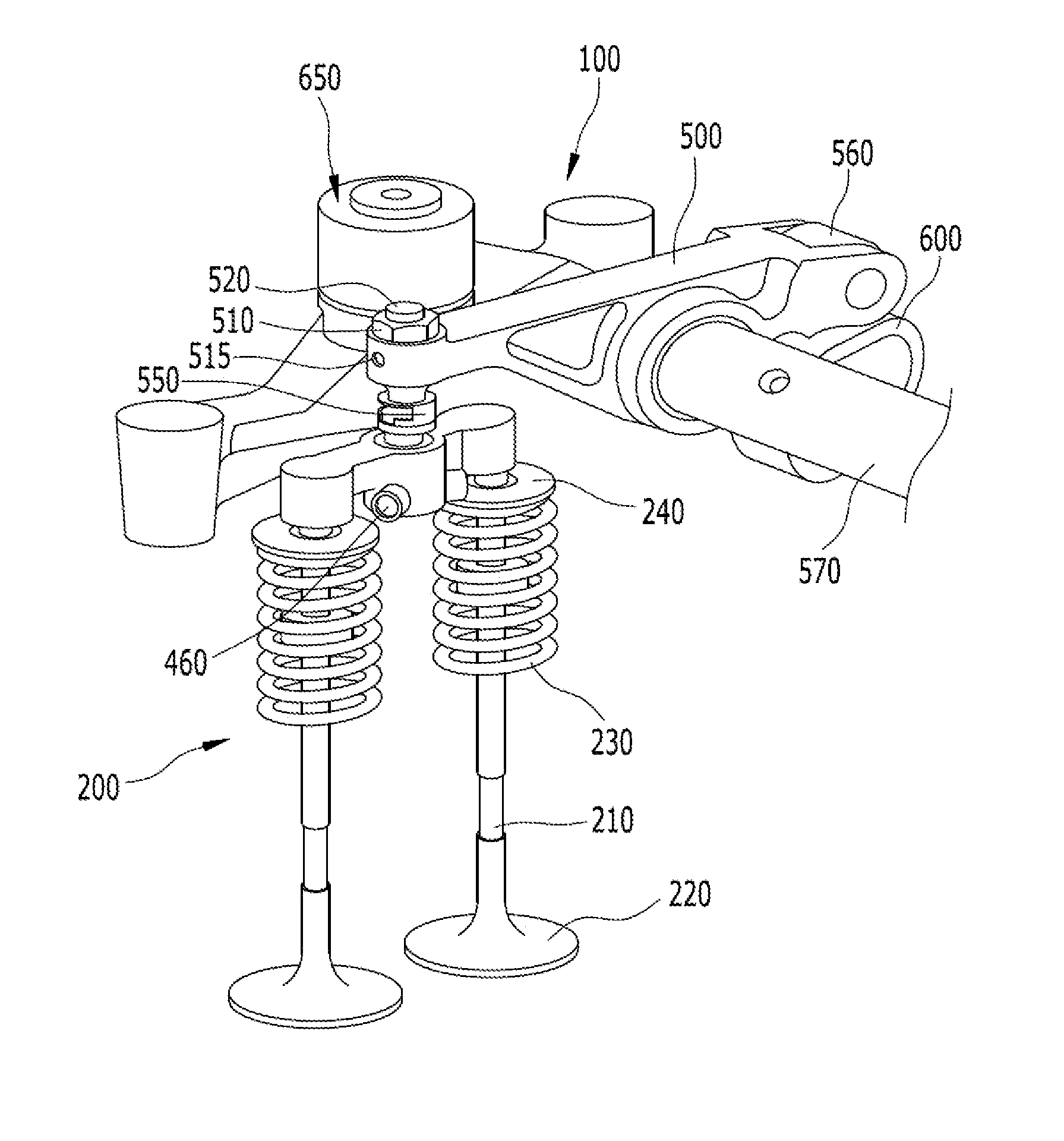
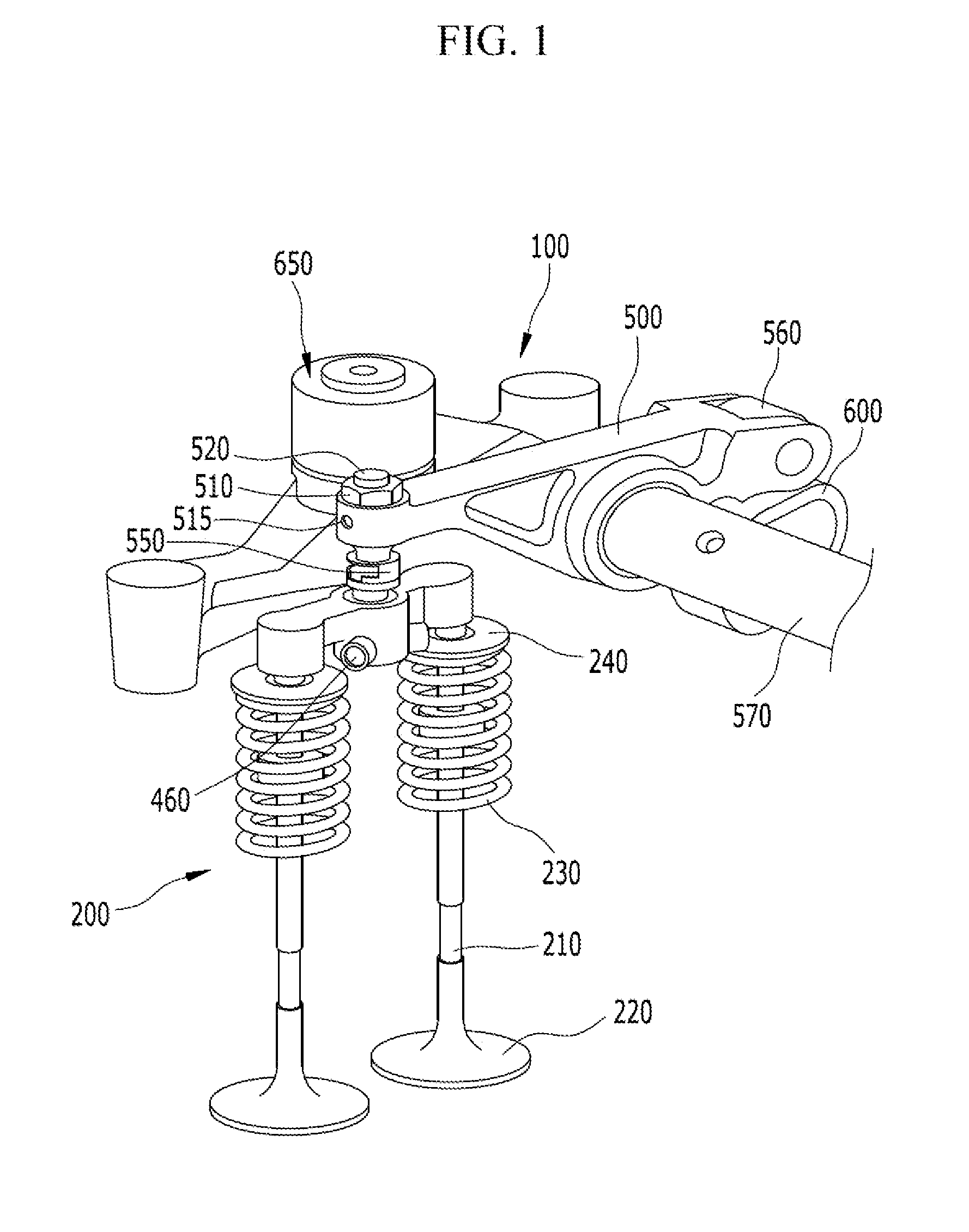
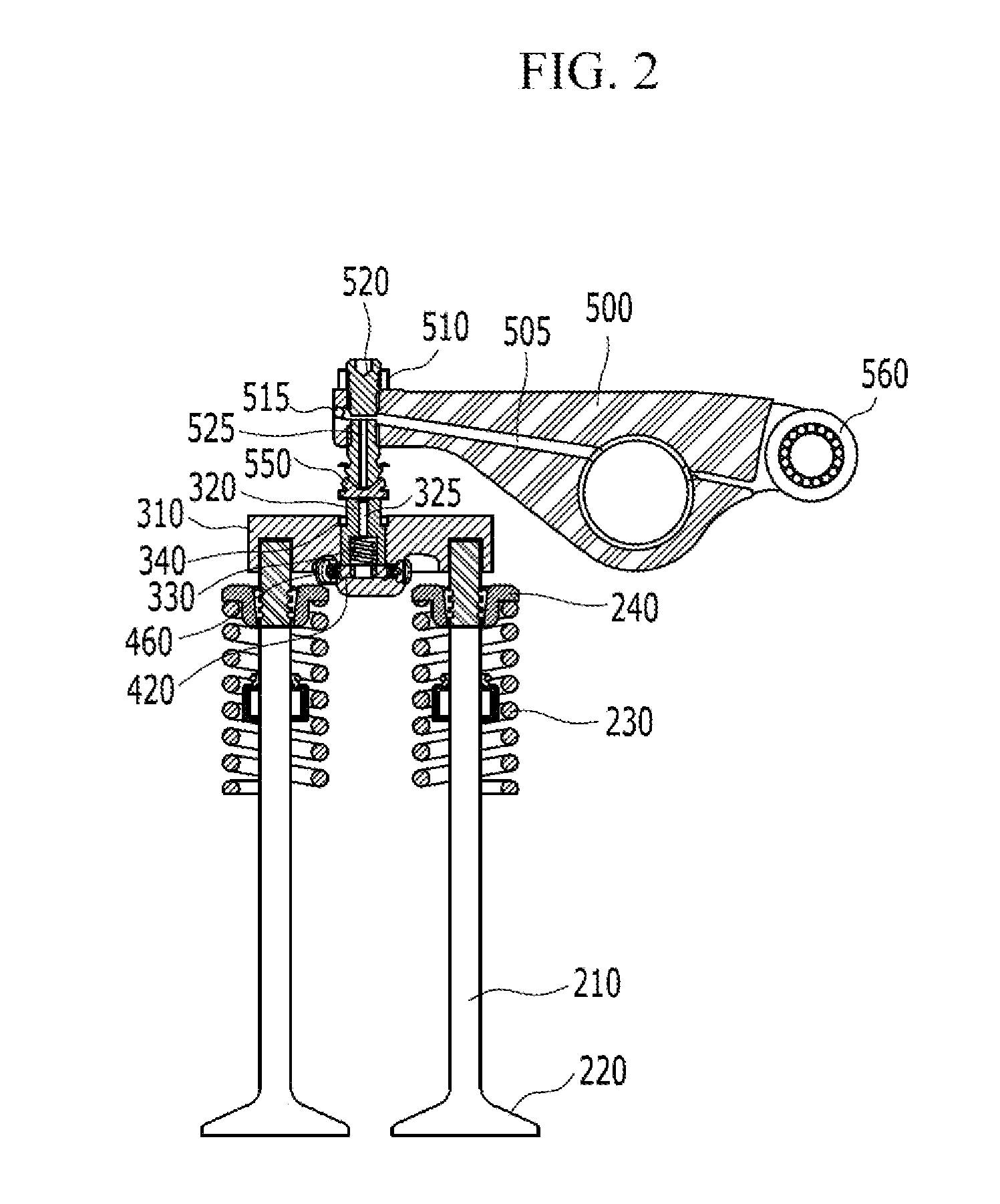
[0031]FIGS. 1-2 show a variable valve lift apparatus 100 including a integrated variable valve actuator assembly according to various embodiments of the present invention. FIG. 3 is an exploded perspective view of an actuator device 350, a variable control device 400, and a valve bridge 310 according to various embodiments of the pres...


PUM


Abstract

A integrated variable valve actuator assembly of a variable valve lift apparatus may include a rocker arm rotating on a rocker shaft and including an oil supply line with selectively provided oil, a fastener penetrating the side of the rocker arm and discharging oil supplied from the oil supply line through the oil passage, a valve bridge located at the bottom of the fastener and pressurizing valves, an actuator device including an actuator piston being inserted in the valve bridge and formed with an oil supply passage, and an actuator spring being inserted in the actuator piston and providing the actuator piston with elastic force, and a variable control device located at the bottom of the actuator piston and adjusting the heights of the actuator piston by a movement generated by the hydraulic pressure of oil supplied from the oil supply passage.

Description

CROSS-REFERENCE TO RELATED APPLICATION[0001]The present application claims priority of Korean Patent Application Number 10-2010-0119803 filed in the Korean Intellectual Property Office on Nov. 29, 2010, the entire contents of which application is incorporated herein for all purposes by this reference.BACKGROUND OF THE INVENTION[0002]1. Field of the Invention[0003]The present invention relates to a integrated variable valve actuator assembly. More particularly, the present invention relates to a variable valve actuator assembly integrated with a valve bridge that comprises a variable control device and an actuator device at the lower end of the valve bridge and changes the height of the actuator device by selective supply of oil.[0004]2. Description of Related Art[0005]An internal combustion engine generates power by burning fuel in a combustion chamber in an air media that is drawn into the chamber. Intake valves are operated by a camshaft in order to intake in the air, and the air ...

Claims


Application Information

Patent Timeline
IPC IPC(8): F01L1/34
CPCF01L1/053F01L1/181F01L2820/033F01L2105/00F01L1/267F01L2305/00
Inventor YOON, SEOCK JOONGKIM, KYUNG MO
Owner HYUNDAI MOTOR CO LTD
Features
  • Generate Ideas
  • Intellectual Property
  • Life Sciences
  • Materials
  • Tech Scout
  • Unparalleled Data Quality
  • Higher Quality Content
  • 60% Fewer Hallucinations
Learn More