
Radiation detection device, system and related methods

Inactive Publication Date: 2012-05-31
WEINBERG IRVING
View PDF0 Cites 20 Cited by
  • Summary
  • Abstract
  • Description
  • Claims
  • Application Information

AI Technical Summary

Problems solved by technology

Global terrorism presents a dire threat to the United States in particular.
Of all of the terrorist threats presented by global terrorism, the most vexatious and insidious are homeland radiation threats.
A successful detonation of a nuclear bomb could potentially destroy entire cities and create a radioactive cloud which disperses radiation over hundreds of square miles.
The humanitarian strife, economic devastation, and widespread fear that a successful nuclear or atomic bomb attack would create are incomprehensible.
Less destructive but nonetheless still catastrophic improvised weapons such as “dirty bombs” or radiological dispersal devices likewise present a potentially serious terrorist threat.
While it is widely believed that the number of fatalities that would result from a dirty bomb would be limited, it is generally agreed that the event would cause widespread panic and crime, contaminate properties, and require costly cleanup efforts.
Recent instances of special nuclear material (SNM) smuggling in Europe suggest that we do not have the luxury of time to delay before deploying effective systems.

Method used


Image

  • Radiation detection device, system and related methods
  • Radiation detection device, system and related methods
  • Radiation detection device, system and related methods

Examples


Embodiment Construction

[0021]Reference will now be made in detail to exemplary embodiment(s) and method(s) of the invention as illustrated in the accompanying drawings, in which like reference characters designate like or corresponding parts throughout the drawings. It should be noted, however, that the invention in its broader aspects is not limited to the specific details, representative devices and methods, and illustrative examples shown and described in this section in connection with the exemplary embodiments and methods.

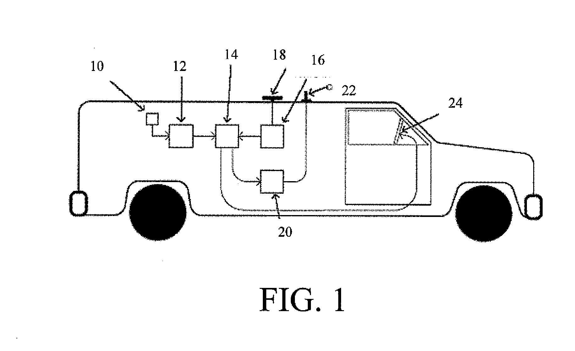
[0022]Referring now more particularly to the drawings, there is shown in FIG. 1 a radiation detection system according to an embodiment of the invention. The system is carried on a roving vehicle such as a truck or van, as shown. Alternative vehicles and other transportation means may be employed, such as automobiles, buses, SUVs, airplanes, helicopters, boats, and others. Although not shown in FIG. 1, the battery, generator, or motor of the vehicle may serve the dual purpose of pow...


PUM


Abstract

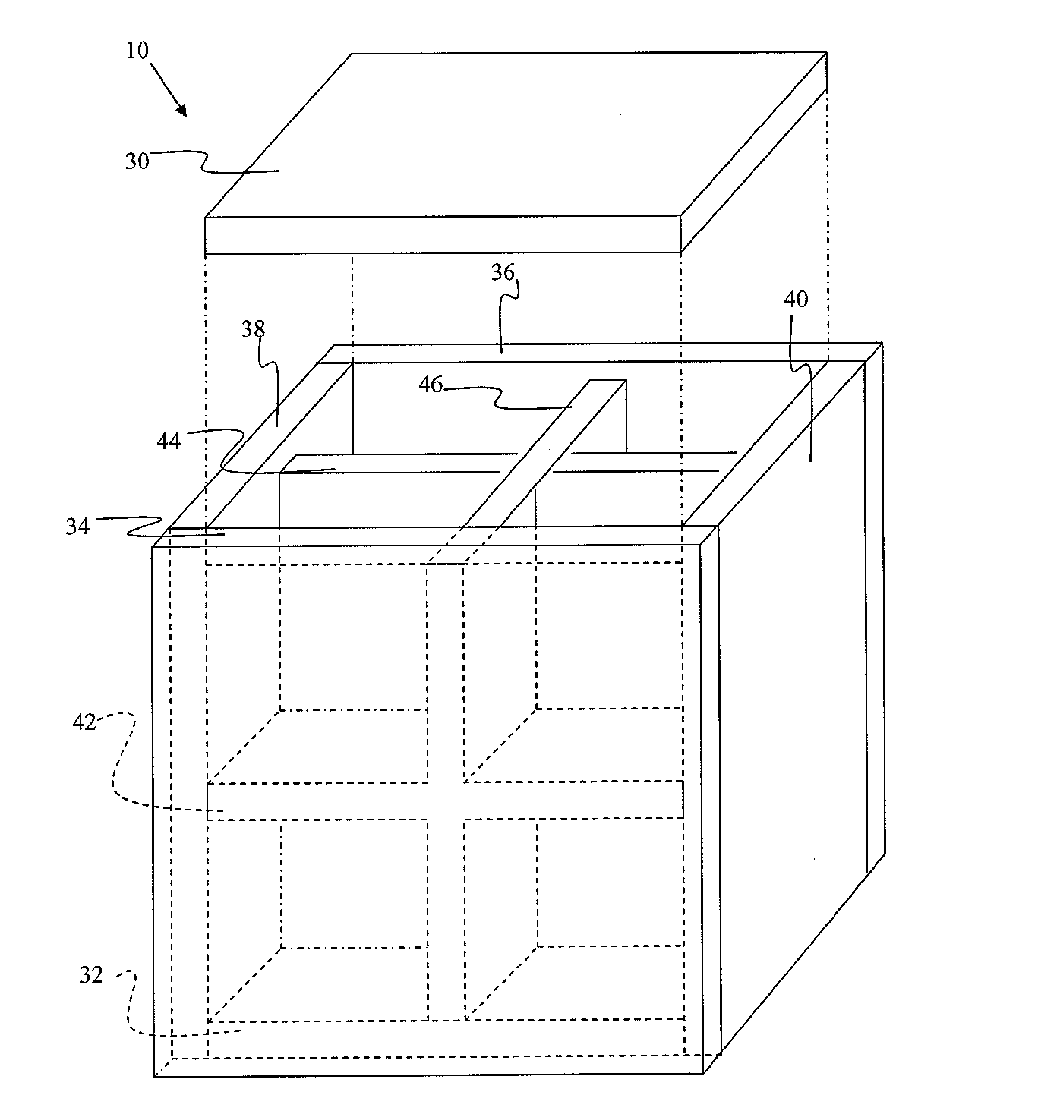
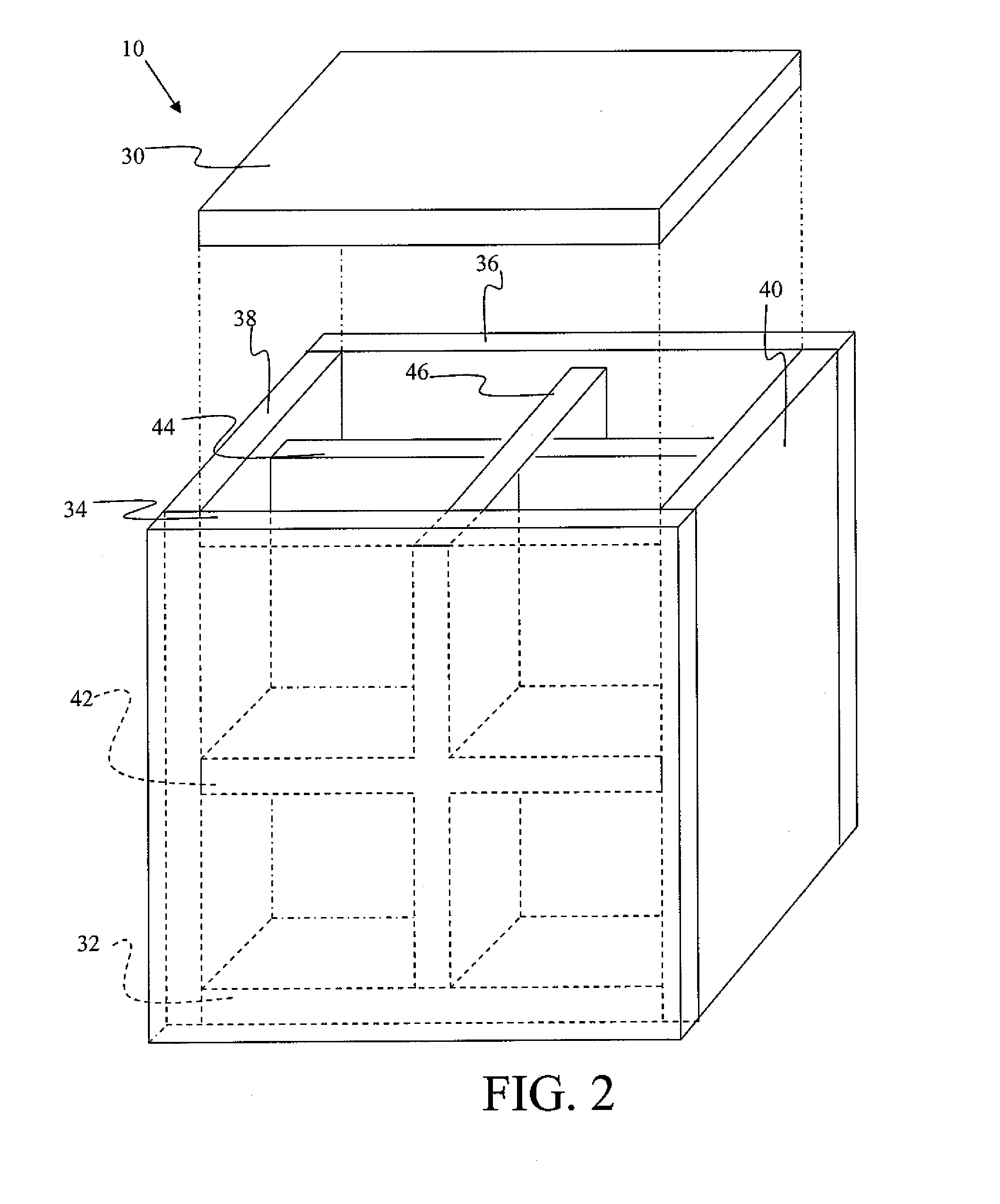
An omni-directional sensor device is provided for detecting radiation emission sources, such as nuclear and atomic weapons and dirty bombs. The omni-directional sensor device is constructed as a three-dimensional structure formed of a plurality of walls of gamma ray detector arrays. The walls face in multiple directions to establish omni-directional sensing of incident gamma rays from substantially all directions. As constructed, a first wall of the device intercepts an incident gamma ray at a first location. The gamma ray experiences a Compton scattering effect whereby a deflected gamma ray is emitted into the inner chamber of the device before intercepting a second wall of the device at a second location. The first and second locations can be used to trace the location of the emission source. Also provided are radiation detection systems including the omni-directional sensor devices, and methods of locating a radiation emission source.

Description

CROSS-REFERENCE TO RELATED APPLICATIONS[0001]This application claims the benefit of priority under 35 U.S.C. §119(e) of U.S. Provisional Application No. 60 / 903,310 filed Feb. 26, 2007 entitled “Innovative configurations of radiation detection and characterization methods,” the complete disclosure of which is incorporated herein by reference.FIELD OF THE INVENTION[0002]The present invention in its exemplary embodiments relates to devices, systems and methods for detecting and locating radioactive materials and weapons, and finds particular applicability to the field of homeland security.BACKGROUND OF THE INVENTION[0003]Global terrorism presents a dire threat to the United States in particular. Of all of the terrorist threats presented by global terrorism, the most vexatious and insidious are homeland radiation threats. In a worse case scenario, the radiation threat would involve a nuclear or atomic weapon nefariously smuggled into the United States. A successful detonation of a nucle...

Claims


Application Information

Patent Timeline
IPC IPC(8): G01T1/20
CPCG01V5/0075G01V5/26
Inventor WEINBERG, IRVING
Owner WEINBERG IRVING
Learn More