Method and apparatus for detection of ionizing radiation

a technology of ionizing radiation and apparatus, which is applied in the field of method and apparatus for detection of ionizing radiation, can solve the problems of limiting the applicability of techniques, low efficiency of x-ray tubes at such low photon energy, and low number of x-rays per unit power supplied to the tubes, so as to reduce the load on the x-ray tubes, reduce exposure time, and increase the efficiency of x-ray tubes

Inactive Publication Date: 2005-02-15
XCOUNTER
View PDF14 Cites 19 Cited by
  • Summary
  • Abstract
  • Description
  • Claims
  • Application Information

AI Technical Summary

Benefits of technology

A further advantage of the present invention is that if broadband radiation is used for the detection, there is less need of thick filters, the efficiency of the X-ray tube is increased, the load on the X-ray tube can be lowered, and the exposure time can be reduced (due to the higher X-ray photon flux).
A still further advantage is that if the photon energies employed are high enough such that variations in the image captured originate essentially only from Compton scattering in the object, these variations are due to the density of the object only, provided that the object thickness is constant, or known and corrected for. This is true since the attenuation coefficient for Compton scattering at photon energies of 10-300 keV is only weakly dependent on atomic number and photon energy. This is in sharp contrast to photoelectric absorption, which is heavily dependent on energy, and particularly on atomic number.
A yet further advantage of the present invention is that the X-ray image obtained is a shadow image of the density variations in the object. This image can be combined with a conventional X-ray image, which illustrates a combination of density and elemental composition (Z) variations in the object. From the two images a third image may be deduced illustrating only the elemental composition (Z) of the object.
Preventing Compton scattered radiation from being detected may be performed by means of a one-dimensional gas ionization detector including two electrodes, between which an ionizable gas is located, and a radiation entrance arranged such that said ionizing radiation enters said detector sideways between the electrodes, and electrons liberated by interaction between the ionizing radiation and the gas are accelerated in a direction essentially perpendicular thereto, wherein the distance between the electrodes is kept short to essentially only allow radiation collimated in a plane between the electrodes to ionize said gas. The distance between the electrodes may be below about 2 mm, preferably below about 1 mm, more preferably below about 0.5 mm, and most preferably between about 0.1 mm and 0.5 mm. The electrodes may be 1-50 cm, and preferably 3-10 cm, deep (in the direction of the incoming X-ray radiation).
The applicant has recently begun to verify the invention experimentally and good contrast has been observed using a wide X-ray spectrum of high energy X-rays, at which conditions a conventional detector system would not be capable to see any structure at all. It is believed that the above-described one-dimensional gas ionization detector discriminates more than 99% of the scattered photons; and by proper design it is assumed that about 99.9% or more of the scattered photons can be prevented from being detected.

Problems solved by technology

A problem with the known kind of approach is that most X-ray tubes have low efficiency at such low photon energy as 20 keV, i.e. the number of X-rays per unit power supplied to the tube is low.
Also, the relatively low flux affects the exposure time in an adverse manner, i.e. makes it long, which obviously limits the applicability of the technique.
The strong energy dependence E of the photoelectric absorption attenuation coefficient μPE results in an undesired narrow dynamic range of the object suitable for X-ray imaging.

Method used


Image

  • Method and apparatus for detection of ionizing radiation
  • Method and apparatus for detection of ionizing radiation
  • Method and apparatus for detection of ionizing radiation

Examples


Embodiment Construction

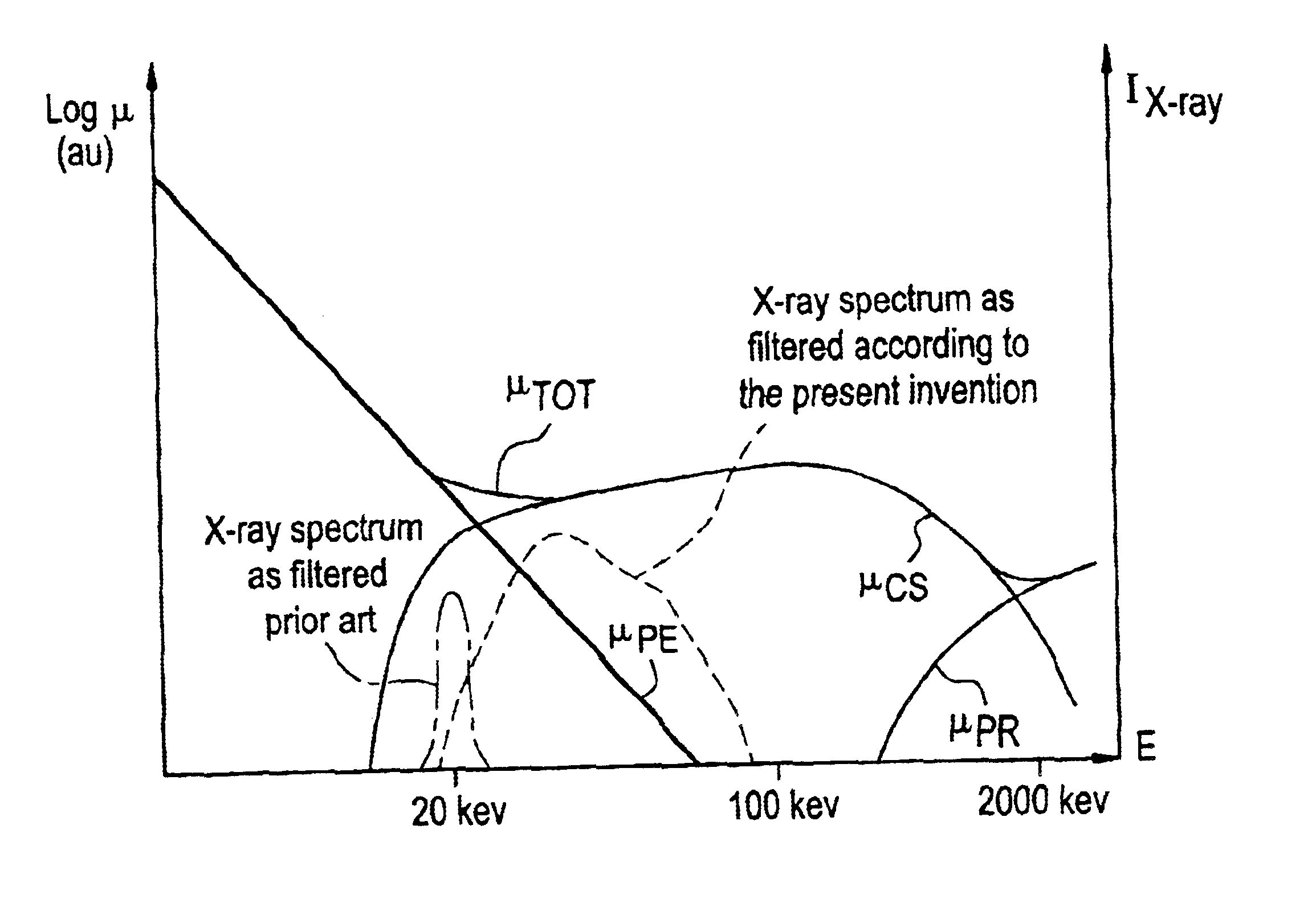
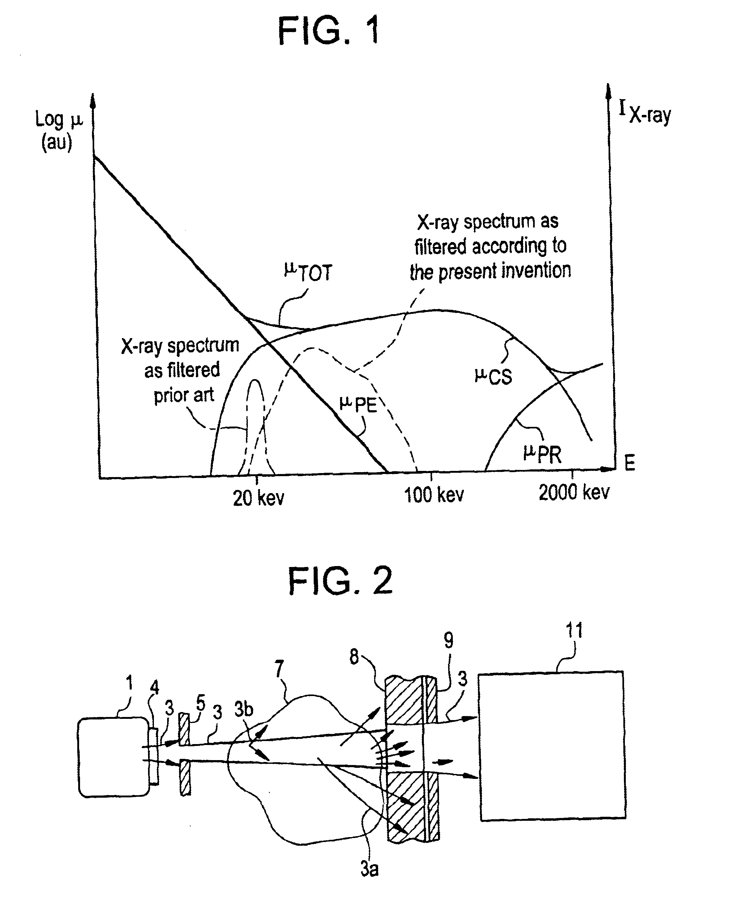
As can be seen in FIG. 1, which is a schematic diagram illustrating photoelectric absorption, Compton scattering, pair production and total attenuation coefficient μPE, μCS, μPR, μTOT, for human soft tissue as a function of X-ray photon energy E, the photoelectric attenuation coefficient μPE decreases as a power law with photon energy, and at about 25 keV the Compton scattering attenuation coefficient μCS is comparable with the photoelectric absorption attenuation coefficient μPE. Between about 30 and several hundred keV the Compton scattering attenuation coefficient μCS is completely dominating, whereas at higher photon energies (in the order of 1 MeV) the probability for pair production is increasing rapidly, and becomes the dominating interaction process. Further, it is noted that the Compton scattering attenuation coefficient μCS is almost constant between photon energies about 30 and several hundred keV. While FIG. 1 is illustrating an example only for human soft tissue, the re...


PUM

PropertyMeasurementUnit
distanceaaaaaaaaaa
distanceaaaaaaaaaa
distanceaaaaaaaaaa

Abstract

A method for detection of ionizing radiation comprises the steps of (i) directing ionizing radiation towards an object to be examined; (ii) preventing Compton scattered radiation, preferably at least 99% of the radiation Compton scattered in said object, from being detected; and (iii) detecting ionizing radiation spatially resolved as transmitted through said object to reveal a spatially resolved density of said object, wherein said ionizing radiation is provided within a spectral range such that more, preferably much more, photons of said ionizing radiation are Compton scattered than absorbed through the photoelectric effect in said object to thereby reduce the radiation dose to said object.

Description

FIELD OF THE INVENTIONThe invention relates to a method and an apparatus for detection of ionizing radiation.BACKGROUND OF THE INVENTION AND RELATED ARTRadiographic imaging detectors comprising an array of small sensors to capture a radiation-generated image are well known in the art. A collimated radiation beam is intensity modulated as it passes through a radiation-absorbing object and the transmitted beam as detected thus represents an inverted image of the absorption by the object, which in turn is related to the elemental composition, density, and thickness of the object.The contrast and spatial resolution in captured X-ray images are deteriorated by X-rays scattered from the object being imaged. Anti-scatter grids or so-called Bucky grids, which absorb the scattered X-rays, while passing through the transmitted X-rays which have not interacted with the object, have been used extensively during a long period of time, see e.g. U.S. Pat. No. 1,164,987 issued to Bucky 1915, U.S. P...

Claims


Application Information

Patent Timeline
Patent Type & Authority Patents(United States)
IPC IPC(8): A61B6/02A61B6/00G01N23/04G01T1/00G01T1/18G01T1/185G01T1/29
CPCA61B6/4035A61B6/482A61B6/483A61B6/4291G01T1/2928G01T1/2935A61B6/502A61B6/00
Inventor FRANCKE, TOMSOKOLOV, SKIFF
Owner XCOUNTER
Why Eureka
Try Eureka