System and method for X-ray generation

a technology of x-ray and x-ray tubes, applied in the field of x-ray sources, can solve the problems of large and expensive facilities, drawbacks of x-rays produced in common x-ray tubes, and limitations in their use,

Inactive Publication Date: 2006-03-21
GENERAL ELECTRIC CO
View PDF12 Cites 18 Cited by
  • Summary
  • Abstract
  • Description
  • Claims
  • Application Information

AI Technical Summary

Problems solved by technology

The X-rays produced in common X-ray tubes have drawbacks that pose limitations in their use.
Moreover, such radiation typically comprises fixed polarization, incoherent radiation that is not tunable.
Synchrotron-generated X-rays also have certain limitations.
In addition, such sources require high energetic electron beams, which in turn require large and expensive facilities.
However, current ICS based X-ray sources are typically very large and complex.
These lasers are very complex and require vast numbers of optical elements to operate.

Method used


Image

  • System and method for X-ray generation
  • System and method for X-ray generation
  • System and method for X-ray generation

Examples


Embodiment Construction

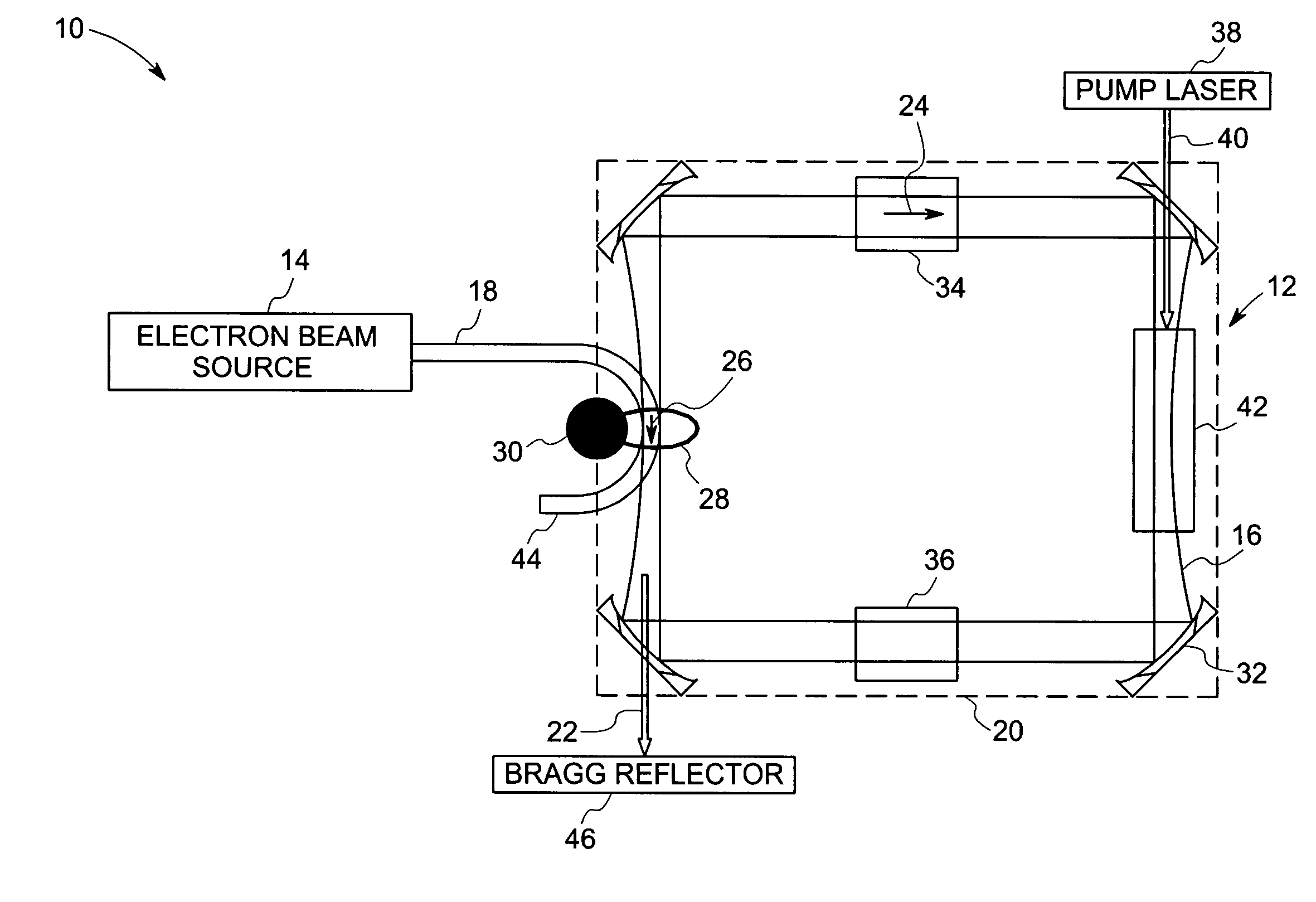
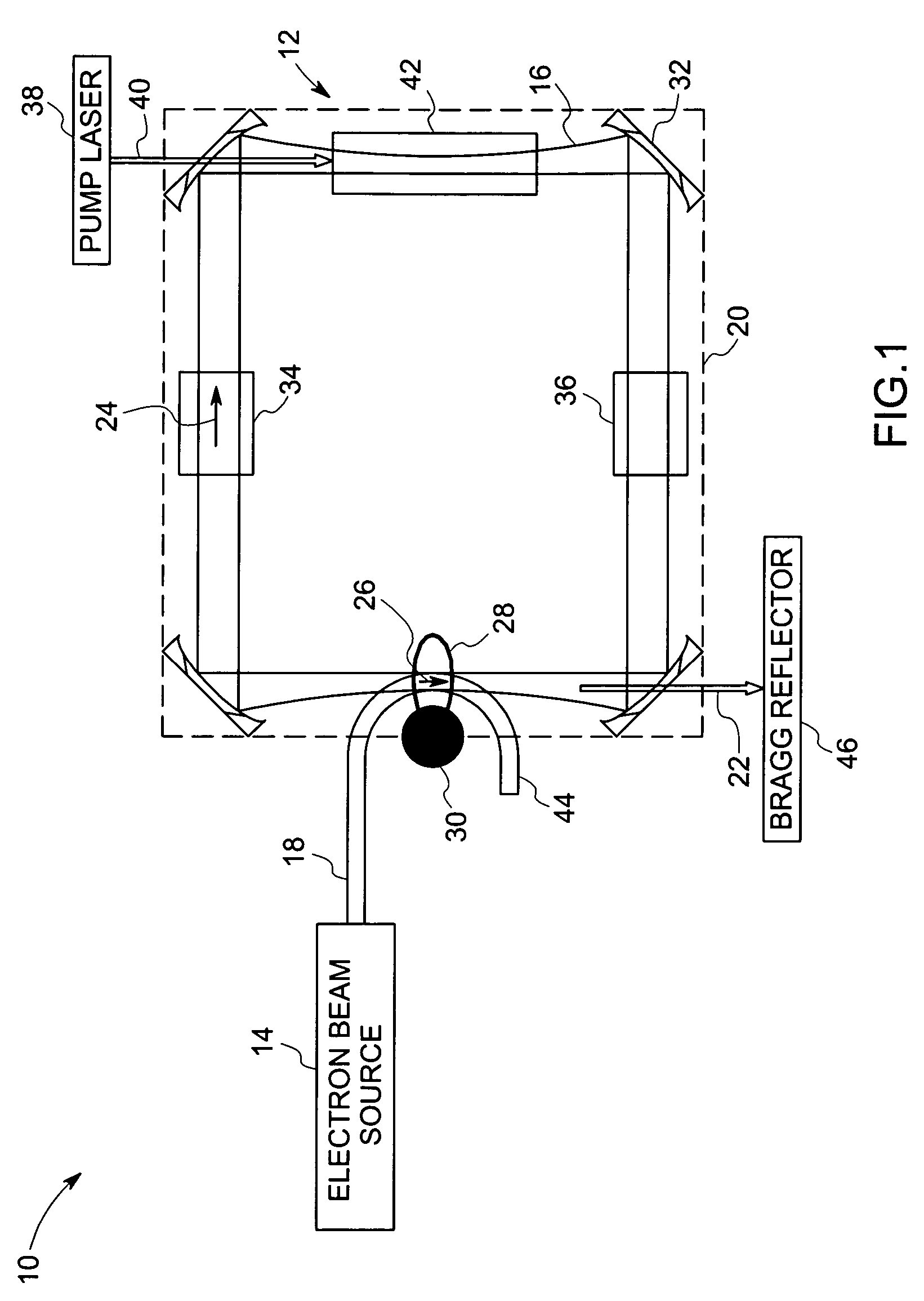
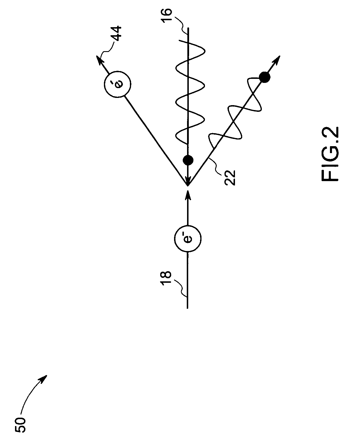
[0012]Referring now to FIG. 1, an ICS based system 10 includes a laser 12 and an electron beam source 14. The laser 12 generates optical pulses 16, while the electron beam source 14 generates and accelerates a pulsed electron beam 18 to relativistic speeds. As discussed in greater detail below, the optical pulses 16 of the laser 12 are directed in a direction opposite to the direction of the pulsed electron beam 18 such that the two collide within the laser cavity of the laser system 12, generating X-rays by ICS.

[0013]In particular, in the illustrated embodiment, the laser 12 includes laser cavity 20 in which the X-ray radiation is generated, as discussed below. Optical pulses 16 are introduced into the cavity 20, and collide with electron beam 18 from the pulsed electron beam source 14. By ICS, then, X-rays, represented generally by reference numeral 22, are generated and directed from the laser cavity 20. Again in the embodiment illustrated in FIG. 1, the optical pulses 16 travel ...


PUM


Abstract

The invention provides a system for generating X-rays via the process of inverse Compton scattering. The system includes a high repetition rate laser adapted to direct high-energy optical pulses in a first direction in a laser cavity and a source of pulsed electron beam adapted to direct electron beam in a second direction opposite to the first direction in the laser cavity. The electron beam interacts with photons in the optical pulses in the laser cavity to produce X-rays in the second direction.

Description

BACKGROUND[0001]The present invention relates generally to X-ray sources, and in particular to a technique for generation of X-rays based on inverse Compton scattering.[0002]For X-ray generation, conventional X-ray sources generally rely on either the Brehmsstrahlung radiation or synchrotron radiation. In the former case, radiation is produced when energetic electrons are decelerated by heavy materials as in common X-ray tubes. Where synchrotron radiation is desired, radiation is produced by ultrahigh energy electron beams passing through magnetic undulators or dipoles in a storage ring synchrotron source. The X-rays produced in common X-ray tubes have drawbacks that pose limitations in their use. For example, Brehmsstrahlung radiations are generally of relatively low power, and comprise long pulses or a continuous wave. Moreover, such radiation typically comprises fixed polarization, incoherent radiation that is not tunable. Synchrotron-generated X-rays also have certain limitation...

Claims


Application Information

Patent Timeline
Patent Type & Authority Patents(United States)
IPC IPC(8): H01S4/00H01S3/083H01S3/91G21K1/00G21G4/00H01J35/00H01S3/00H05G2/00H05H1/00H05H13/04
CPCH01S3/083H01S3/1109H05G2/00
Inventor LAWRENCE, BRIAN LEEFILKINS, ROBERT JOHNLORRAINE, PETER WILLIAM
Owner GENERAL ELECTRIC CO
Why Eureka
Try Eureka