Eureka AIR delivers breakthrough ideas for toughest innovation challenges, trusted by R&D personnel around the world.

System and Method for Driving a Switch

Inactive Publication Date: 2012-05-31
INFINEON TECH AG
View PDF3 Cites 12 Cited by
  • Summary
  • Abstract
  • Description
  • Claims
  • Application Information

AI Technical Summary

Benefits of technology

[0007]The foregoing has outlined rather broadly the features of an embodiment of the present invention in order that the detailed description of the invention that follows may be better understood. Additional features and advantages of embodiments of the invention will be described hereinafter, which form the subject of the claims of the invention. It should be appreciated by those skilled in the art that the conception and specific embodiments disclosed may be readily utilized as a basis for modifying or designing other structures or processes for carrying out the same purposes of the present invention. It should also be realized by those skilled in the art that such equivalent constructions do not depart from the spirit and scope of the invention as set forth in the appended claims.

Problems solved by technology

Such a property poses difficulties because the switch transistors appear as short circuits before the power supply system is fully biased, thereby causing high currents to be generated at the startup of the power supply.
The use of transformers, however, is expensive.
When JFETs are used, however, such bootstrapping techniques are difficult to apply.
For example, when the internal supply voltage of the power supply system is low at startup, the JFET switches may not operate because the voltages required to allow the JFETs to switch on and off has not yet been developed.
If the JFET switches do not operate, then the internal supply voltages needed to make the switches operate cannot be generated.

Method used


Image

  • System and Method for Driving a Switch
  • System and Method for Driving a Switch
  • System and Method for Driving a Switch

Examples


Embodiment Construction

[0018]The making and using of various embodiments are discussed in detail below. It should be appreciated, however, that the present invention provides many applicable inventive concepts that can be embodied in a wide variety of specific contexts. The specific embodiments discussed are merely illustrative of specific ways to make and use the invention, and do not limit the scope of the invention.

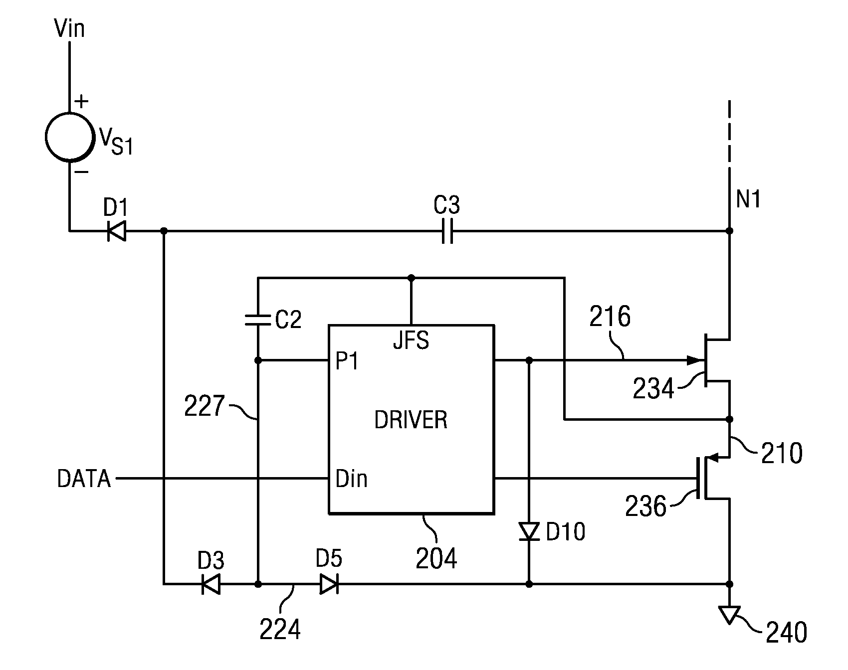
[0019]The present invention will be described with respect to various embodiments in a specific context, namely switch drivers in switched mode power supply systems. Embodiments of the invention may also be applied to switch drivers in other electronic applications such as solar inverters, telecom, servers and uninterruptible power supplies.

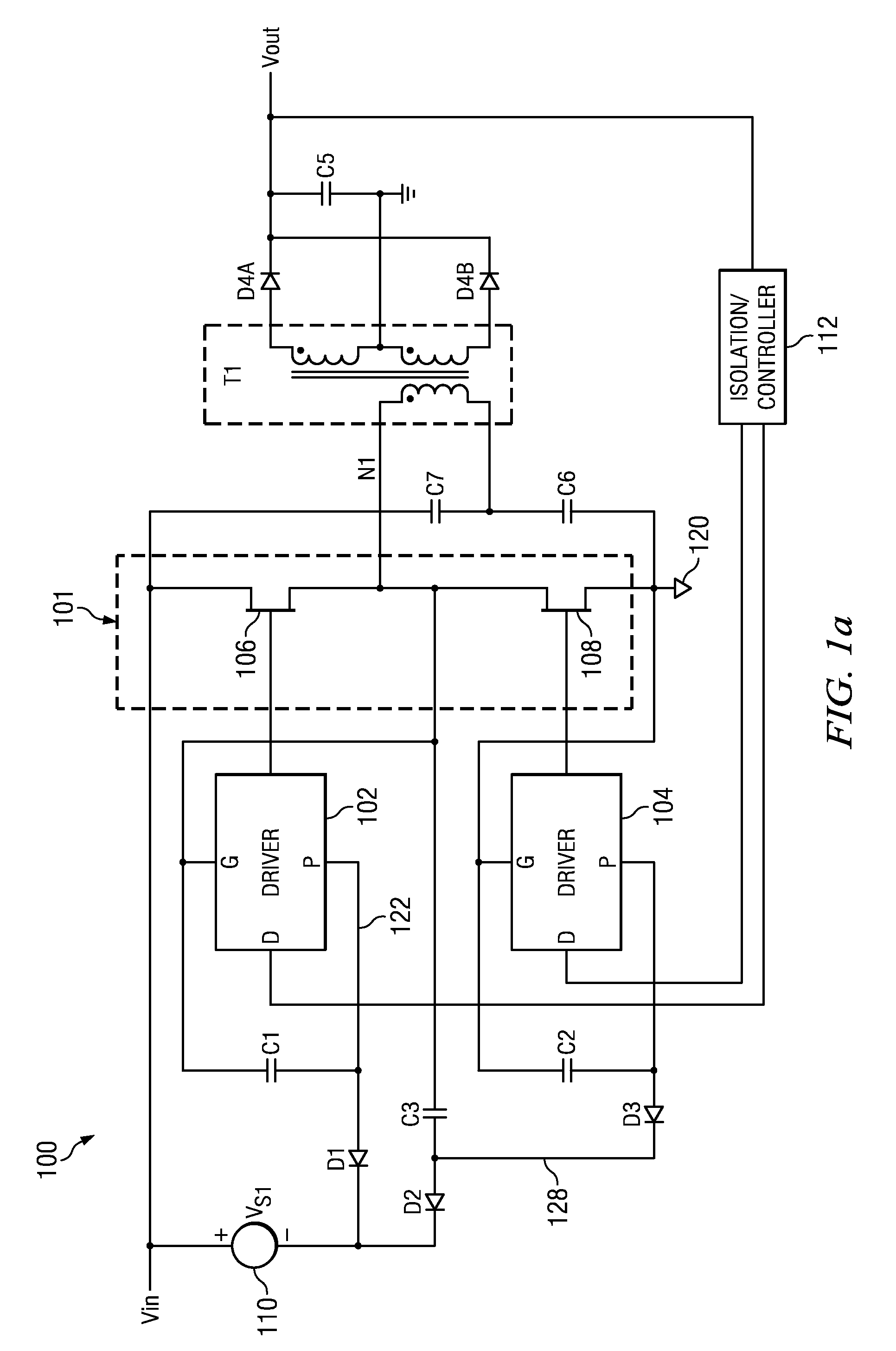
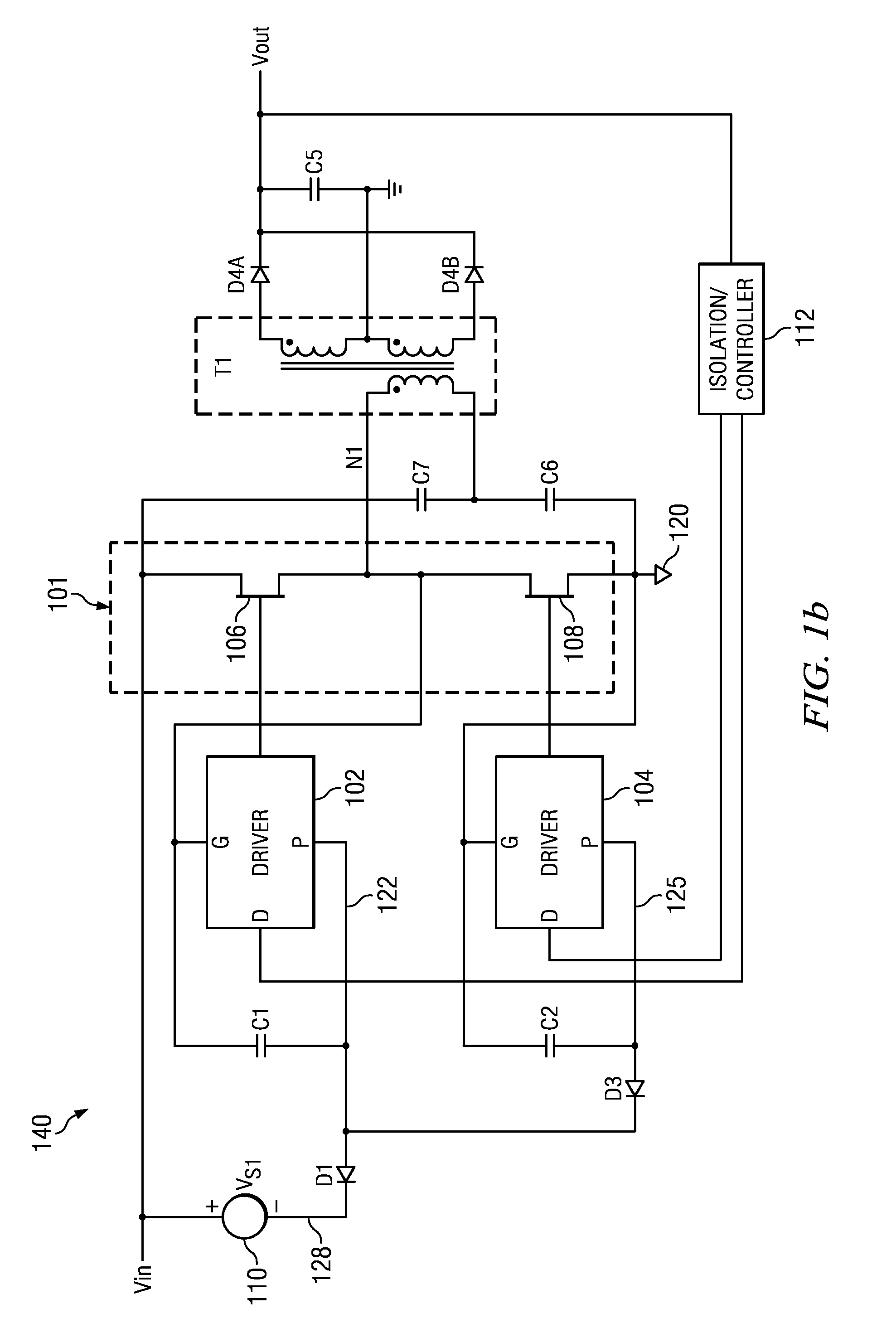
[0020]FIG. 1a illustrates power supply system 100 according to an embodiment of the present invention. Input voltage Vin is applied across half-bridge 101 circuit having high-side switch 106 and low-side switch 108. In an embodiment, each switch 106 and 1...


PUM


Abstract

In accordance with an embodiment, a circuit for driving a switch includes a driver circuit. The driver circuit includes a first output configured to be coupled to a gate of the JFET, a second output configured to be coupled to a gate of the MOSFET, a first power supply node, and a bias input configured to be coupled to the common node. The switch to be driven includes a JFET coupled to a MOSFET at a common node.

Description

CROSS-REFERENCE TO RELATED APPLICATIONS[0001]This application relates to the following co-pending and commonly assigned U.S. patent applications: Ser. No. ______, filed on ______ entitled “System and Method for Boostrapping a Switch Driver,” and Ser. No. ______, filed on ______ entitled “System and Method for Driving a Cascode Switch,” which applications are hereby incorporated herein by reference in their entirety.TECHNICAL FIELD[0002]The present invention relates generally to electronic circuits, and more particularly to a system and method for driving a switch.BACKGROUND[0003]Power supply systems are pervasive in many electronic applications from computers to automobiles. Generally, voltages within a power supply system are generated by performing a DC-DC, DC-AC, and / or AC-DC conversion by operating a switch loaded with an inductor or transformer. In some power supply systems, combinations of switches are arranged in a bridge configuration such as a half-bridge, full-bridge, or a...

Claims


Application Information

Patent Timeline
IPC IPC(8): H03K5/24H03K3/00
CPCH02M1/08H03K17/691H03K17/063H02M3/33553
Inventor DRAXELMAYR, DIETERNORLING, KARL
Owner INFINEON TECH AG
Why Eureka
Eureka Blog
Learn More